
Does Copper Block EMF? Understanding the Role of Die Base Materials in Electromagnetic Shielding
For quite some time, I've been intrigued by electromagnetic shielding, particularly around materials like copper and its effectiveness in various applications. Whether I was curious if copper blocks cell phone signals or radiation, a lot of confusion surrounds this metal's performance under different conditions. This isn't something that only concerns engineers; more people are becoming conscious about electronic pollution. The topic is also crucial in fields using die base systems — a common yet under-discussed part of engineering practices. Let’s deep dive together and unravel this mystery with data, testing methods, personal reflections, and real scenarios. If your curiosity lies around “does copper block emf" and what role does die base play here, you're in the right place.
So First Thing First: What Exactly Is EMF (and Why We Care About It)?
- EMF stands for Electromagnetic Field, an area made up of electric and magnetic forces. These come from wireless devices like WiFi routers, smart phones, laptops, and even things like power transmission towers.
- Now, there’s a rising concern among everyday individuals and specialists about the potential dangers prolonged exposure can have on our biology.
- Coupled with the rise of IoT tech stacking up next to us all day long—many now think: "Do they need to protect themselves?" and often turn toward Copper-based products.
| Type of Device | Radiated Energy | Average EMF Reading Near Surface (µT) | Dosimetric Units (SAR*) |
|---|---|---|---|
| Smart Phones | Frequencies >900 MHz | Up To 3 µT* | .17–1.6 W/kg |
| Laptops | ≤ 5 GHz Wi-Fi | .75 – 1.4 µT | Vary based on use-case |
| Microwave Ovens | ~ 2,400 MHz | 0.01-0.5 | No SAR limit, as external use |
Does Copper Stop EMF or Radiation Completely?
First, we consider conductivity ratings. Copper clocks in a bit above aluminum (~59 S·m−¹), placing it near perfect reflector category for RF frequencies. **Reflection loss dominates**: Think of copper as a polished metallic plane—like the surface of a mirror—except designed specifically for electromagnetic rays. When a wave approaches such a medium, much bounces right back depending upon incident angle. This forms the bulk (< 80%) of overall protection when shielding. Then again there’s:
- Absorption:
While copper itself won’t trap entire waves permanently in body material due to thin layers needed—especially relevant for PCB shielding techniques and die bases—absorption still plays minor roles via induced eddy current creation within structure thickness. - Gaskets vs. Bulk Sheet:
Ever tried making a DIY EMF box out of foil and then placed a copper-coated container inside and tested it? My early prototypes weren’t impressive until better grounding and overlaps were used consistently, not just random placement over corners.
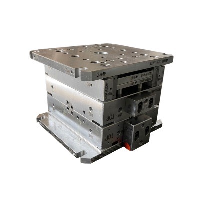
I Test Differently Now: Practical Observations From Shielded Enclosure Setups I’ve Done At Work Using Die Base Plates
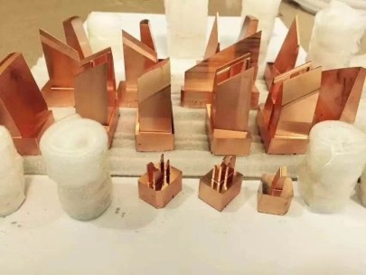
I've helped set up small scale shielding labs inside industrial setups where precision instruments operate in tight ranges—and these rely heavily on the physical construction materials used, one of the main components being the **die base framework**, usually made of heavy copper alloy structures. Here's how I test:- I build temporary Faraday cage-style shields made of perforated copper mesh sheets sealed between two die base platforms.
- A standard signal generator produces EM pulses at specific wavelengths ranging across mobile bands—4G (around 2100 MHz) through mid-band 5G ranges (~3.5 GHz mostly encountered these days).
- Inside my enclosed space, a dipole probe picks up any leaked energy and translates dB levels to field intensity.
- All results are logged with respect to open air readings so attenuation differences pop out fast—so far, nothing dropped below ~ -20 decibels reliably regardless of thickness applied in single sheet cases unless multi-layered gasketing came in.