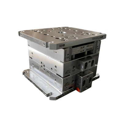
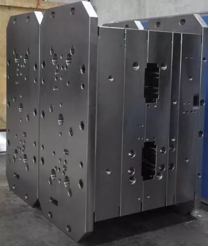
If you're into the world of precision mold manufacturing, then you've probably come across the dilemma of selecting copper blocks—especially in applications that require high-accuracy base molding solutions. **My** initial foray into the industry started with choosing between different materials for my very own mold base components, and over the years, I’ve learned just how crucial it is to choose top-notch copper options when working on mold bases. So today, I’ll take you through how my journey led me down this copper rabbit hole—the what-to-look-for, installation pointers, pitfalls to avoid, plus why it really does make a massive difference in projects like Tile Base Molding. Let's dig right in.
What Are the Roles of Copper Blocks in Precision Mold Base Manufacturing?
To kick things off, let's clarify what copper's job actually is inside these mold designs. In most applications, particularly high heat environments or intricate part shaping setups, copper blocks are chosen for their superior heat dissipation characteristics.
- Promote even temperature transfer across complex surfaces
- Prevents warping or stress fractures during cooling phase
- Aids in maintaining mold tolerances within microns
Bonus Tip: If you work primarily with thermally-sensitive plastics, consider alloys that mix tungsten with pure-grade copper—these hybrid composites are especially effective at handling localized hot-spots better than generic grades found on commodity sites.
| Copper Type | Purpose | Typical Use Case |
|---|---|---|
| Oxyfree High-Conductivity (OFHC) | Excellent heat diffusion; good machinability | Used in medium-temperature molds with minimal abrasive elements involved |
| Invar-backed | Eco-nominal expansion control due t0 coefficient balancing against adjacent metals | Durable in long production run systems with frequent cooling changes |
The Link Between Copper Grade Quality & Tool Life Expectancy
Honestly speaking—and trust me, trial-error has taught me this—I used to purchase whatever “standard issue" copper block got recommended by a distributor without understanding the implications. Big rookie mistake!
You’d think any shiny chunk of conductive metal will work… but no. Here’s where quality diverges performance outcomes:
- Porosity can wreak havoc if micro void content exceeds ~4% per ASTM B176
- Degree of impurity traces drastically influences thermal expansion rate behavior
Always insist on a certification sheet with each order stating its exact electrical and thermal conductivity figures before purchasing large lots!.
Troubleshooting Common Pitfalls When Integrating Copper With Aluminum-Based Mold Systems
One situation I’ve seen repeated over the decade involves mismatched assembly when trying integrate high-conductivity copper insert blocks alongside lightweight 7075-T6 mold support plates—particularly common when fabricating parts meant fort ile based mold structures.. You'd expect smooth operation but unless alignment tolerances compensate for differential wear rates—you may find yourself replacing joints way ahead schedule .
In fact, the single biggest pain-point early-on came when using improperly anodized cavities around copper zones—the surface interaction accelerated oxidation along interface lines after only two hundred shots during testing. Not fun! To save yourself headaches:
- Double seal overlapping areas between metallic substrates exposed to steam environments
- Ensure all threads tapped inside copper sections use HRC rated tooling
If the system requires post-machining heat treatments, pre-cook those custom-fit coppers inserts inside nitrogen-blasted furnaces to remove residual moisture beforehand—skimp this & cracks start showing up within three months of continuous usage cycle...
Nailing The Proper Mount Technique – A Step By Step Guide On How to Install Base Cap Moulding
#1Select your tools
This should seem obvious—except, too often people skimp here and suffer later down road.
#2 Align Your Joints: Avoiding Air Leaks That Cost Hours Fixing Down Stream Later
- Lift one end & tap lightly on dryfitting edge aganst frame corner until snug fit
- Demand shifts toward customizable copper-infused nanocomposite panels embedded modular systems.
NOTE:< br/>Avoid placing excessive glue near copper-coupled joints—they swell differently vs aluminum, leading gaps eventually pop open six moths out unless handled upfront.
#3 Test Before Permanent Installation
Now here comes one golden nug get: After preliminary placement and before fastening anything permanent... Step away. Then return in full light environment to spot shadow discrepancies indicating slight bow distortions... These little inconsistencies? Left unchecked? They'll throw entire alignment off during curing process. Yep been ther e myself once :(Tip #4 – Reinforce Only Necessary Zones, Not Entire Runs
Believe me I went full gorilla-torch weld on extra brackets during one big project thinking that was safer. Big fail! Stress concentrated so badly I had warped segments within first two weeks! Lesson: Apply reinforcement only in corners and mid-span spans exceeding ten inchs between main support beams.Predictions For Future Industry Shifts In Thermal Dissipation Methods And Impac t o n Copper Usage In Mold Designing Techniques
Now stepping away slightly form practical how-t os... let me toss some speculation grounded reality abt possible tech developments expected hit sector next few yeas...I see strong signs pointing toward increasing interest graphene-dipped ceramic blends being tested by European labs. They boast same heat conduction stats traditional Cu alloys offer while adding abrasion-resist properties not typically linked copper. Although still pricy today—give em couple five yrs they become viable commercial option. What will this shift mean current industry reliance solely cu-based mold base solutions? Most likey scenarios:
| Tools Required | Optional Alternatve | < / tr>
| Cheep Tape Measurer | |
| Mitre Saw | < td>Straight Line Cutting Attachment For Drill Gun|


