
Does Copper Block EMF? Exploring the Role of Mold Base in Effective Electromagnetic Interference Shielding
So I found myself standing there in my workshop, holding this oxidized piece of copper in one hand and a section of mold base trim on the other wondering… does copper block emf, actually? It's not something most DIY-ers or engineers really talk about — but I've seen enough electrical weirdness from unshielided circuits lately that it’s worth digging into.
The more I worked with different types of metal mold bases (which, by the way, I'll explain later in better detail), I started noticing some curious effects around electromagnetic interference shielding. Turns out, this isn't just a side-note issue anymore—it's becoming critical for modern building practices, electronics manufacturing, industrial setups and even in personal builds where WiFi signal integrity is key for daily use stuff around the house. So what exactly does mold base have to do here? Why does oxidized copper come into play, and how should we be cutting base mold corners anyway when installing shielded environments using those materials?
Mold Base as a Platform for EMI Reduction Applications
- The structure supports the integration of shielded components such as grounding brackets.
- It helps define optimal locations for placement of EMI-absorbent materials like specialized polymers or coated fabrics during design layout phase in tool room planning workflows.
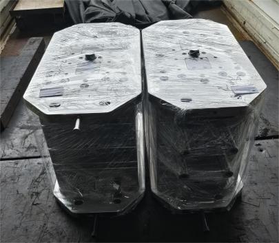
In many cases, when I start building test setups with metallic mold components or even repurposing old industrial dies as lab test equipment housings, I've found that the structural role of mold base can also become part functional—especially once we're talking RF isolation zones or Faraday cage simulations built inside compact test areas. Whether in plastic mold shops or electronics enclosures labs—it serves as the framework onto which EMI mitigation solutions mount or bond directly.
What Happens With Oxidized Copper Surfaces?
If you’re serious about long term EM radiation management, surface conductivity changes are something you can’t overlook — like with Oxized Copper layers. As the natural patina begins taking hold over time or under aggressive conditions, it starts forming a dielectric film that actually diminishes skin effect efficiency across ultra-thin sheet metals typically used for high GHz-range applications.
Comparison Table: Cleaned vs. Oxized Copper Surface Efficiency in 2.4GHz Range
| Copper Type | Average dB Attenuation @2.4GHz | Skin Resistance |
|---|---|---|
| Newly Machined Unoxidized | 68dB | .5 ohm/meter squared |
| Surface Oxidized After Exposure | 52dB | 3.2 ohms/sq-m |
When working on shielding for Wi-Fi 6/7 frequency domains particularly at shorter ranges—oxidation plays a much bigger part in degradation than folks generally expect without testing.
Evaluating Conductivity & Practicality of Copper Use Against EMI Fields
I always get people ask “does copper block emf, though?" Let’s break that idea down. While pure metallic copper definitely exhibits strong conductance properties due to its atomic density and low magnetic permeability, full scale shielding depends largely on installation methods beyond just presence of copper plates near radiated noise zones. Especially important if using flat mold-base backplate systems instead of full cavity boxes. Also thickness, shape, edge treatments—critical when dealing above mid-frequency bands.
Cutting Mold Base Corners Accurately Without Compromise
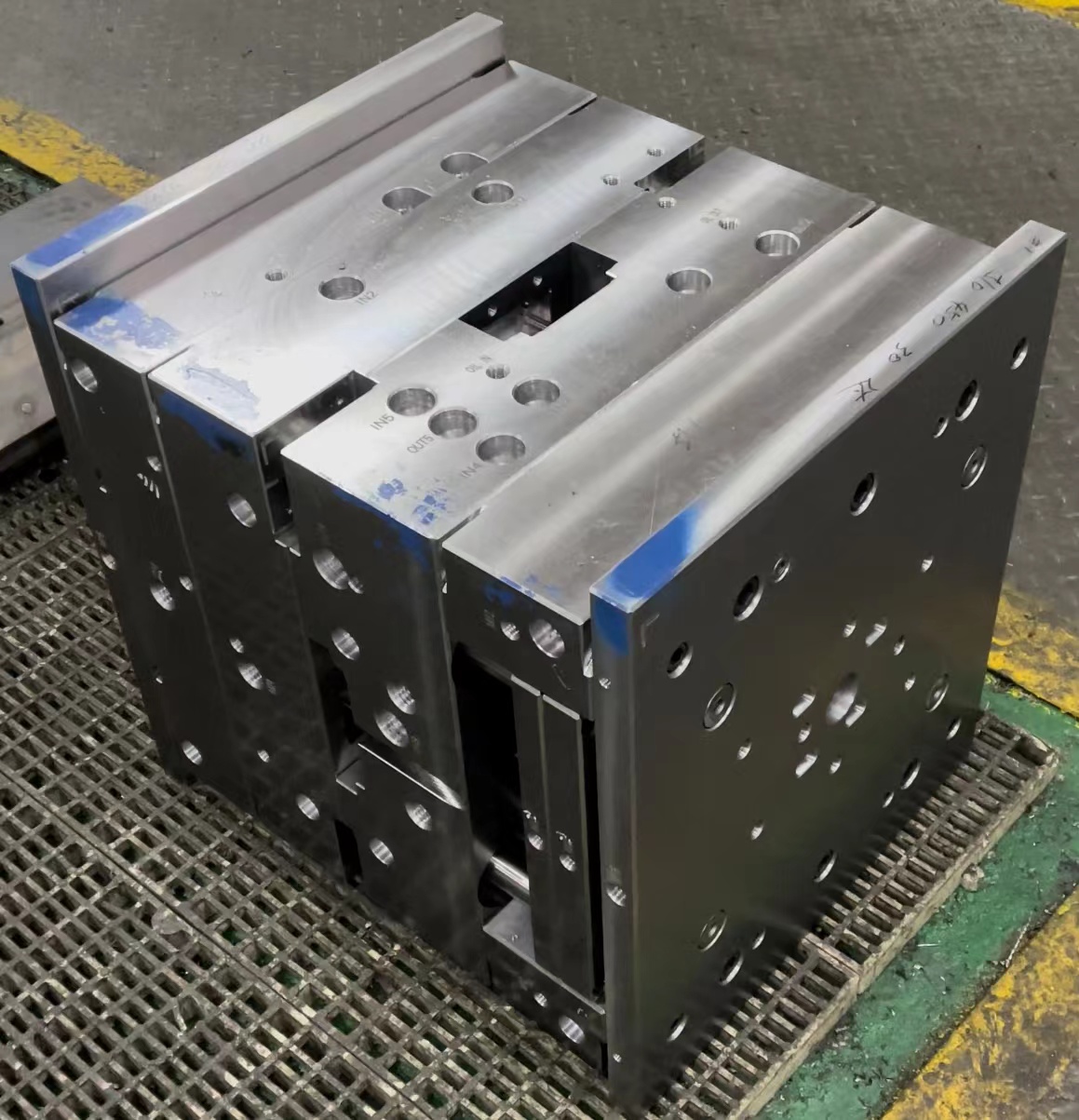
Funny thing I learned recently—how precise miter cuts on standard **mould base** material affect EMI sealing continuity more significantly than initially thought when integrating them alongside grounded foils, rubber seals and overlapping panels that create zero-gap shielding surfaces between sections of assembled structures.
- Dual-Check Measurement: Measure twice, cut once—but maybe better three times if tight corner fitting needs absolute precision
- Select Proper Blade Pitch For Profile Depth; finer teeth for thin walls and angled composites avoid chip outs common in aluminum base substrates
- Add Post-Cut Chamfering On Inner Faces; this allows seamless interface when combining conductive tapes and compression-fit contact points
Differences Between Molded and Non-Molded Base Systems in Real World Scenarios
I’ve noticed major advantages in prefabricated systems over modular panel-based ones. One big advantage being that the pre-stressed form factors reduce joint-related field leakage issues especially when mounted perpendicular against wave propagation axes—something traditional segmented base boards tend to ignore until field measurements start revealing hot-spots later during compliance audits.
- Material Conductance Level Variability (copper > steel/aluminum depending usage environment)
- Cleaning Maintenance Practices to Preserve Metal Interfaces From Dust Or Corrosion Effects Over Long Runs
- Mold Seam Line Precision—Even 1 mm misaligned seams may leak significant portion of sub THz emissions affecting nearby circuit operations if no proper gasket buffer layer provided
- Oxize Copper states—surface treated alloys can degrade faster under extreme humidity / chemical exposure altering final shielding values overtime even if installed perfectly first month.
Hazards and Misapplications When Using Mold Bases For RF Environments
Despite benefits, improper setup could lead more harm than good—I recall this one test build with anodized mold frame I borrowed off a CNC mill waste pile—didn’t work so well for lower frequencies below 1MHz where eddy-current paths matter a lot because insulation layers completely interrupted ground paths.
Warning Flags To Check Before Proceeding
If any component fails to pass simple resistance connectivity checks below ~1 Ohm total path measurement between each segment of mold framework, it likely will underperform at RF levels regardless how visually tight your installation appears.
In summary — Does copper really block EMF effectively on its own? Yes—but in context! It performs best only if combined with appropriate mechanical integration techniques including optimized base mold construction principles and clean material handling standards especially when oxidization risk comes in during extended outdoor operation cycles. Also learning the proper way you should be how to cut base moulding corners might make a real world measurable change in end-product effectiveness versus merely aesthetic considerations. If you aim at actual EMI control, don’t skip prep steps or overlook aging dynamics over material life cycles. Stay sharp and test often!