
The Ultimate Guide to Choosing High-Quality Copper Blocks for Precision Mould Base Applications
Alright, let's get this out the way early — selecting high-quality copper blocks is no simple task, especially when it's meant for critical mould base systems used in injection molding or die-casting processes. If you’re anything like me (or even slightly concerned with long-term reliability and cost-efficiencies), you know how crucial copper components are to overall performance. So here I am sharing everything I have learned through personal experimentation, countless material breakdowns, and real shop floor observations over the past decade. The goal? Help others find better copper blocks by understanding the technicalities, specifications, and application contexts.
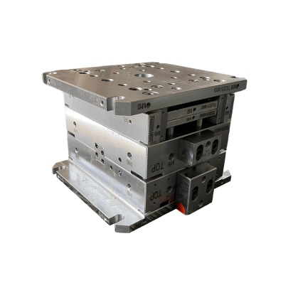
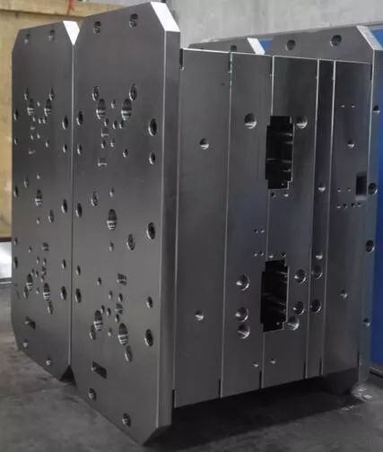
Understanding Mould Bases and Where Copper Fits In
Let’s begin by establishing the baseline – what a *mould base* really refers to in most manufacturing contexts. A typical plastic injection molding set requires precise structural rigidity combined with temperature control mechanisms, which often rely on materials exhibiting optimal heat dissipation capabilities.
In some of these configurations, copper plays a vital role. Unlike tool steel that makes up bulk of the mold structure, **copper blocks**, particularly those with superior purity and isotropic thermal properties, can offer unmatched heat removal benefits from highly loaded regions in cavities or near ejector pin placements. It’s not unheard of for specialized copper parts, like *cove base moldings*, designed specifically to conform to cooling contours around sharp radii or tight undercut geometries — making installation easier while still improving process stability significantly.
| Component Material | Primary Function | Common Usage Cases |
|---|---|---|
| Mold Steel | Main structural component | Bulk cavities, standard cores |
| Copper | Heat distribution / transfer agent | Hot spots cooling channels, localized ejection areas |
Grades of Copper & Their Relevance in Manufacturing Blocks
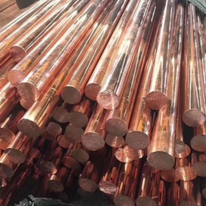
Clean grades are non-negotiable if one plans to source quality **copper blocks**. For the uninitiated, Oxygen-free electronic (OFE), Phosphorus-deoxidized (PDA-497), Tellurium-bearing C14500, and Beryllium-coppar varieties represent key candidates depending on specific operational parameters such conductivity demands vs mechanical load exposure. My go-to recommendation tends toward high purity ETP copper but certain cases call for alloying additives based off corrosion resistance needs.
If I was building something custom — say an intricate insert needing electrical conductivity alongside thermal dispersion qualities — then I might choose silver-bearing types at elevated conductances (~97% or above) even if that pushes my per-block cost skyward compared against more economical brass-alloy options. Just depends on how many rejects you plan tolerate due residual hot spot entrapment during shot cycle time!
- ELECTROLYTIC TOUGH PITCH C110
- OXYGEN-FREE COPPER (ASTM F68)** – Ideal where low oxygen content matters (e.g welding preclusion, vacuum chamber sealing etc).
- DON’T GO NEAR RECYCLED SCRAP IF THERMO-ELEMENT PERFORMANCE MATTERS!
Select Dimensions Carefully - A Real World Measurement Case
I remember working on one particular system requiring a square profile fitting precisely into a multi-layer assembly frame; the dimensions called for exactly 50.0 centimeteRs per edge, leaving literally 1 micrometer tolerances before interface friction caused catastrophic alignment drifts under cyclic pressure stresses. The initial supplier tried handing us recycled sheets, leading too much variation after annealing treatments... bad mistake that resulted wasted machining hours because of inconsistent thicknesses throughout individual lots.
Quality Inspection Practices Prior to Installation
A big part what separates seasoned buyers versus novice ones is how they screen each incoming raw batch. From my experience conducting microhardness testing to ultrasonic density analysis helps uncover internal voids invisible upon surface observation yet impactful once subjected extreme thermal cycles or mechanical compression strains.
- Visual checks: Are surfaces scratch or oxide covered?
- X-Ray spectroscopy confirms composition uniformity within sample lot.
- Hip testing (hot isostatic pressing proof) recommended prior large scale deployment.
Fabrication & Integration Tips Straight From My Workbench
If you’re fabricating a square plate measuring half a meter along its borders (*a square plate of copper with 50.0 cm sides*) prepare adequately—cutting tools dull FAST and clamps require rigid setups since softness leads distortion risks especially if handling thicker plates than .25". What also works better than standard carbide end mills (in my case): polycrystalline diamond-tipped ones when facing ultra-smooth requirements were demanded post-CNC finish work across cavity mounting pads intended direct engagement metallic interfaces.
**Key takeaway: Keep coolants running consistently during machining steps or warpage happens almost without fail due uneven heating buildup.**- Ensure full support table structures when routing edges;
- Use lower rotational speeds initially till cut depth stabilize;
- Verify concentric flatness via optical gauges between every phase changes (annealed → aged → EDM finish etc.)
Trends Driving Change and Why Your Choice Really Matters
Comeback trend favoring higher efficiency toolroom standards is seeing copper usage increase again especially among high-value prototyping segments relying fast iteration models. Because **copper blocks** deliver unique thermodynamic advantages unobtainable otherwise, engineers increasingly adopt hybrid approaches wherein steel remains primary structure, while embedded coper regions manage intense localized hotspots inside runners, gates and complex part features otherwise hard regulate through traditional baffle-based designs alone.