The Ultimate Guide to Choosing the Perfect Mould Base and Raw Copper Block for Precision Engineering
For anyone involved in industrial toolmaking or precision diecasting — choosing the right mould base and selecting an accurate raw copper block can be a gamechanger. I have spent over seven years working with CNC-mold bases and conductive materials like copper, and honestly? It's not as straightforward it looks. But don’t worry — if you read everything below step by step, you'll start understanding what goes into a reliable selection that lasts decades.
In This Article:
- Mould Base Essentials You Can't Skip
- Why Choose a Raw Copper Block?
- Key Selection Criteria
- Material Compatibility Factors Between Bases and Metals
- How to Cope with Common Base Molding Issues?
- Recommended Tools & Equipment for Installation
- Tips for Maintaining Base Cap Molding Systems
- Industry Applications (From Real Scenarios I've Witnessed)
Mould Base Essentials You Can't Skip
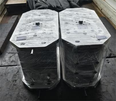
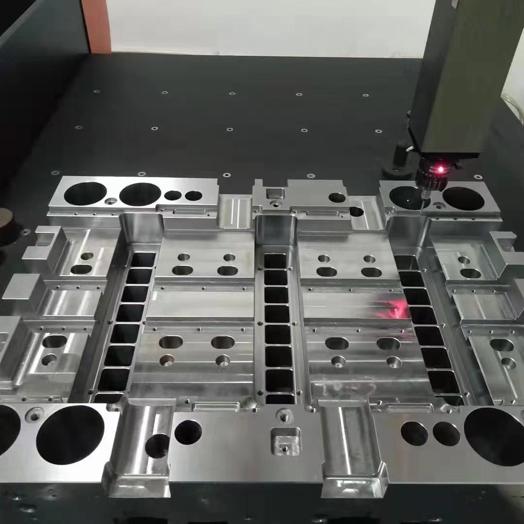
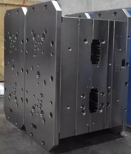
When it comes to injection mold building and structural casting, the mould base acts as the backbone — supporting all components including plates, bushings, cavities and ejector pins. There are generally two main categories in industrial contexts:
- Fully customized mold frames — tailored for high-end, repeat-use scenarios (typically more costlier but long-term worthy)
- Preset template frames — pre-made with standard dimensions used for less specialized jobs (faster turn-around time)
Some Key Points on Mould Frames I've Learnt:
Avoid using aluminum or cast iron frames where dimensional stability is paramount — thermal expansion might cause unwanted shifts. Stick to steel-alloys (preferably hardened ones like SCM435) especially when combined wi**h raw copper blocks* — we’ll go through that next.
Why Choose a Raw Copper Block
In complex molding setups requiring optimal heat dispersion such as insert molding, pressure molds, hot-runner applications—enter the use-case for raw unalloyed copper block usage in cavity structures. Let me walk u**h my own example: On a project last year involving heat-intensive electrical terminals, standard mold metals didn't cut it. Heat distribution had massive dead spots and warpage started emerging at higher throughput speeds.
| Material Type | Thermal Conductivity (W/m·K) |
Common Use Cases |
|---|---|---|
| Copper Block | 380–400 | HPS Cooling Channels, Ejector Areas with High Friction |
| Hardened Steel | ~30–60 | Main Structure Supports and Wear Resistant Inserts |
So the switch to raw copper-based cavites drastically improved uniform cooling which reduced rejection rate to less than 0.1%. If you have high-temp environments consider them early-on during material planning stage.
Main Components to Consider in Material Matching
Here are things i take note before any large investment gets made into base systems:- Metal Expansion rates — mismatch in thermal coefficients between the frame metal (usually alloyed) and inner components (like coper cores) will lead to internal stresses over longterm cycling
- Risk of corrosion: If moisture levels vary in your environment then certain brass-coated or coated blocks might serve batter than unprocessed variants even thogh pure ones may offer better conductivity
Understanding Mold Base & Insert Material Compatibility
While working with hybrid structures — combining copper with standard mold steel isn’t impossible, there *are trade-offs.* Below is a comparison table showing some basic material behaviors you might notice:| Type of Component | Density g/cm³ | Contact Wear Level* | Treatment Recommendations |
|---|---|---|---|
| Raw copper block | ≈9g/cm³ | Moderate to high friction contact wear observed | OILING SYSTEM NEAR INTERFACES |
| Tungsten Mold Frame | 8.2–8.5 | Low abrasive impact under same cycle runs | Lifetime Grease Sealed Bearing Joints recommended |
Problem Solving - How to Cope With Poor Base Molding Fit Issues
Now let me share a little scenario that messed up one of my earlier assignments. During assembly phase, a mismatch occurred between plate depth tolerence (-0.02mm variation on three plates) leading to uneven core support across sections. After some digging, heres what actually worked out to avoid full system rework.- We added custom PTFE shim layers behind mounting zones reducing lateral play caused bu uneven surface planes
- We opted fo**e machining adjustments — recalibrating only two key contact rails (top and mid) allowed us to get back within +/- 0.008 tolerance range acceptable per clients revised specs.
- Took extra steps later on to ensure future builds included tighter quality control checkpoints at vendor’s warehouse itself rather than just incoming inspection
Equipment Recommendations When Installing Copper & Standard Base Elements
Here’s a short list of the equipment i recommend keeping at arms reach:- - Titanium Drill Bits
- → For precision copper milling — these hold sharper longer against softer alloys without chipping easily
- Use oil bath cutting coolant (instead of mist spraying)
- Ensure dust suction near grinding station — fine particles tend too settle fast in air spaces if not evacuated properly!.
Maxing Out Lifespan Through Preventative Maintenance Practices
Once set up, maintenance is often forgotten till it causes breakdown. here are four steps i religiously follow every 90-days or so depending upon intensity level of mold usage- Pulse flush cooling lines quarterly with diluted nitric acid solutins, this removes buildup and mineral clumps from water sources used for thermal managment systems within base assemblies
- Check copper inserts monthly with magnetic gauge tester – excessive erosion points indicate either overload issues oer alignment offset that need correction immedately after batch
What Do Others Typically Do in Practice (Real-World Examples From My Workbooks?)
This one was taken straight from production site records during a collaborative manufacturing run last year in ohio for heavy duty automotive part casts using copper core based systems. *Company Confidentiality maintained*
Final Takeaways on Choosing Your Molding Foundation & Insert Metals Carefully
So there you go—after years dealing with both conventional systems and experimenting with advanced materials like raw **_copper inserts inside rigid mould base setups_, i can safely summarize that proper pairing hinges upon multiple factors including:- • Conductivity Needs Versus Durability Demands.If heat dissipation is critical but wear resistance is low on priority list — choose copper. Otherwise steel stays king.
- >• Ensure you’re checking expansiveness characteristics across different temperature bands, especially if you operate molds in extreme conditions like cryogenic cold forming or superhot diecasts.
- >•Bond strength matters:If you are integrating multiple elements — look for coating options that reduce thermal transfer loss while allowing mechanical interlock to prevent disintegration at high cycles.
Summary Table of Core Ideas Covered Here:
Mold Base |
Raw Copper Insert If temp regulation and consistent heat flow crucial for geometry fidelity and minimal porosity defects – go unalloyed cooper block vs traditional P20 steel or AlCrMo. |
Compatibility - |
Erosion Mitigatiion Strategies – Apply sacrificial platin layer over cooper cores to reduce micro abrasion from sliding steel counterparts — works really great for parts with aggressive ejection mechanics. |
| Note:**A rough estimate shows average life expectnaces around 150K-700K cycles vary based on base type & environmental exposure. | |