
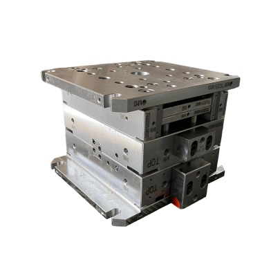
Die Base Manufacturing with High-Quality Tool Steel Plate for Precision Tooling
Hello there! This article comes straight from the heart (and hands) of my experiences in the tooling industry — yes, a real-life engineer talking shop after long hours on the mill and in CAD models. You’re about to read a deep dive into how I design, produce, and evaluate die bases using tool steel plate. I hope this not only helps you grasp what’s really going on here under the press, but inspires your own work with solid fundamentals and maybe even some bold choices.
Selecting Premium Tool Steel for Durable Die Bases
Back when I started off building molds, I didn’t fully understand what separated a decent die base from one that truly stood up over time under punishing pressures. That’s when I learned — or better yet, was shown by many ruined setups and warped guides — that everything began with your choice in material. And no doubt, if it comes down to serious precision stamping or cove base molding applications, nothing works quite like good-grade tool steel.
I've gone with S7 and H13 types for several custom die builds now; they’ve all served well. But if your operation leans heavily into high wear, look closely at hardened A2 as well. Below's a quick reference table showing what properties are relevant for choosing tool steel in critical components:
| Grade | Hardness After Treatment | Toughness Level | Typical Use in Die Making |
|---|---|---|---|
| A2 | 55-62 Rc | Moderate Shock Tolerance | Trim, Forming Dies |
| H13 | 48-58 Rc | Good Fatigue Resistance | Fairlife forging, hot dies |
| S7 | 50-63 Rc | Vibrant Impact Absorption | Heavy-duty impacts & cold form |
- Degree of toughness matters in blank holders, guide pins, etc. Choose carefully;
- Average thermal conductivity plays into cove-based moldings' cycle times;
- Cleaner heat treatments avoid premature failure during dry-lube conditions.
Casting Alternatives vs Machined Tool Steel Plate Usage
In case you've run a project where casting seemed like “easier" route to die frames, then I’m guessing it was probably a pain downstream. While sandcasted aluminum bases do have use cases, such applications tend to favor dies made from forged tool steel slabs cut to blueprint spec in most commercial operations I worked at — and especially those involving CNC-guided cove base molding.
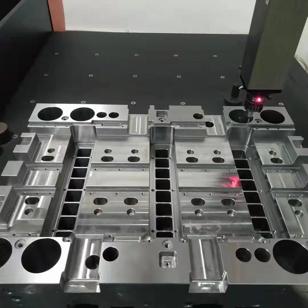
Beyond dimensional accuracy, cutting from plates instead of blanks gives a lot less porosity. In the past six years, every core block alignment nightmare I ever had traced back to a casting that changed shape slightly within two weeks post-machining.
Retrofitting with Standardized Insert Systems: Lessons Learned
Last summer I had to fix a 35-ton progressive punch line for auto body panel production because inserts weren’t seating right across three stations. The previous setup used odd-sized pockets — none followed the same depth standard. After swapping out nearly half the frame to match JIS-standard cavity specs with a uniform finish matching #4 polished surfaces, downtime went wayyy down.
Stick to ISO / DIN insertion norms when possible;
Uniform mounting depths keep tension distribution smooth;
Use surface roughness specs per insert supplier recommendations;
The Unsung Role of Solid Copper Blocks
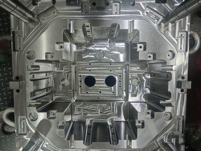
You wouldn't think copper has a place in heavy-duty die construction, unless perhaps...mold cavities for plastic parts with intricate details were involved? Oh yes — particularly those running under high-speed thermoplastic pressure environments with low cooling latency. If done properly, a precisely bonded copper block embedded near cavity edges absorbs excessive flash build-up better than any oil bath can manage.
One example is the small automotive bezel part I helped set-up last October where a single cavity wore down rapidly on two adjacent corners due to insufficient cooling geometry in its first version. After installing custom-inserted bronze-coated copper inserts along the lower section, I noted both longer ejection cycles and sharper corner clarity across the molded batches. Impressive!
Common Alignment Errors When Setting Die Bases on Press Bed Frames
If someone told me five years ago that just setting the frame wrong causes like 38% of our annual scrap loss, I would’ve laughed — till I actually mapped out a full production report myself.
- Don’t rush shimming until the press ram's parallelism checks are zeroed.
- Absolutely never rely on clamps alone – always check the locating slots too. One job failed on account of a missing center lockbar hole!
- A dial gauge should ride top and bottom planes before final fastening. If you don’t catch minor tilt shifts early, you get skewed cavity halves down the line… again – seen it multiple times.
When to Repair Versus Replace Worn-Out Base Sets
It sounds like a business question, but believe me — sometimes your tools will whisper exactly what action to take through simple measurements:
- If plate warpage exceeds .001 mm/2 inches — replace it.
- Elongated bushing clearance above 0.035 inch means re-bore time unless budget constraints hit.
- Oversized ejector rod misalignment leads to uneven part lift-off — repair or scrap.
- Dented leader pin bores are mostly recoverable unless stress-cracked beyond edge.
This also relates directly to maintenance schedules and preventive replacements. My rule-of-thumb formula looks like below – feel free to tweak depending on mold cycles/hour ratios typical for your sector:
| Component Section | Total Lifetime | Metric for Evaluation |
| Top Plate | ~8–10 Years | Gage readings & impact point fatigue marks |
| BOTTOM DIE HOLDER | 7 years | Contact area deviation + clamp wear pattern |
| COPPER LINER INSERTS* | 2 to 5 yrs* | Precision loss around cavity exit path |
Different Industries Call for Unique Surface Treatments
You may think applying surface coating to die frames is just another unnecessary expense, until you're trying cleanout stubborn polymer deposits day after day. Take nitrocarburizing for zinc casting molds, where slight rust formation around runners creates more buildup resistance than we often anticipate in pre-trial modeling phases. Or, how titanium carbide coatings improve hardness values in brass shell forming setups without affecting electrical grounding points.
Conclusion — Building Real, Practical Excellence into Die Base Engineering
To conclude this long-ish write-up: building durable, cost-effective die systems starts and ends at your materials, your tolerances, and how well you monitor their behaviors in real-time applications. It goes further than technical manuals, too — I believe deeply in getting dirty out in the bay so that every calculation we enter reflects tangible, repeatable results down line.
If this piece sparked any fresh thoughts for your current process flow, then great! Whether its revisiting tool steel options, checking your solid copper block placements anew, or even just giving worn bushings a second look this morning before tapping anything out as normal – remember: excellence lies not just in doing the perfect design, but making sure the imperfect bits are managed correctly throughout.
— Me, somewhere drafting between 2AM machine tests & early meetings with molders I trust the most.