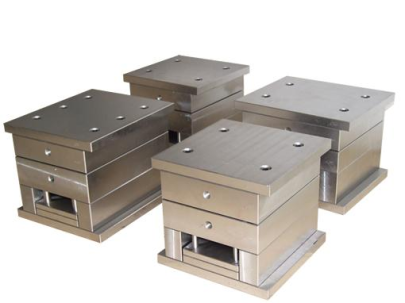
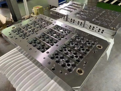
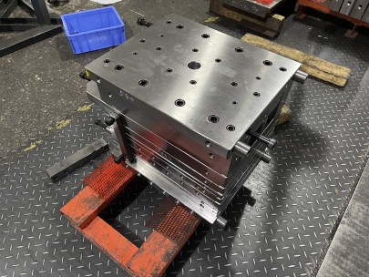
When I first entered the field of **die base** design, especially in **electrical engineering**, most engineers emphasized one key choice: material selection for the backing plate. Among the different alloys available—from **A2 steel** to various copper-based compounds—the one that stood out consistently was **copper plate**. Let’s explore my experience with die base materials and why using a high-conductivity, low-corrosion solution like **copper plate** made all the difference in performance.
The Importance of Selecting the Right Material
I’ve seen projects fail simply because engineers overlooked die plate material quality. A **die base** must maintain dimensional stability while allowing effective heat dissipation, current distribution uniformity, and structural support—three factors directly linked to efficiency in PCB layout, stamping tools, and high-pressure die-casting applications.
I've tried numerous base options like tool steel (**A2 steel**), aluminum-bronze alloys, and phosphor-bronze alternatives over my past few decades. The consistent performer—surprisingly even over many steel composites—is good old **copper plate**, especially when used under specific coating strategies like electroplating (such as learning how **to tin plate copper** effectively, more on that later).
| Material Type | Conductivity | Strength @ High Heat | Machinability | Longevity |
|---|---|---|---|---|
| A2 Tool Steel | Limited | High | Poor | Long |
| Phosphor Bronze | Med | Med-High | Good | Medium |
| Copper Plate | VHigh | Low | Excellent | Varies based on treatment (can be very high if tin plated) |
What Makes a Strong Die Base?
In manufacturing environments that rely heavily on EDM or press-fit applications, having an accurately milled die plate is essential.
- Metallic conductivity must align to your application needs—especially critical in molds handling electromagnetic currents or rapid-thermal cycling tools;
- Mechanical robustness under load matters;
- Thermal fatigue resistance is necessary during repeated expansion & contraction stages.
- Dimensional tolerance across multi-step production processes must meet ISO standards without distortion;
- Last but not least, cost-to-benefit balance per square inch of material used matters too.
I remember a failed die insert project back around ’09. We used hardened carbon plates due to availability, expecting longevity similar to tool steel bases. What happened? Within five weeks of use, our punch die lost alignment accuracy—a flaw traced back not to poor tooling practices, but to excessive electrical resistance in a base incapable of dispersing static properly.
This was one major incident where we went from asking "which alloy can serve well", to realizing it was the base’s inherent conductivity (or lack thereof) affecting process stability.
Why I Use Copper as My Go-To Plate Material in Die Designs
As someone designing molds and dies used extensively in aerospace tooling and micro-weld electrode manufacture—especially those demanding fast current transfer and high thermal control—choosing a highly **conductive metal** such as copper plate just makes sense for the right applications.
Main benefits:
- Rapid conduction and uniform current dispersion improves EDM wear characteristics;
- Tight tolerances can still accommodate complex geometries when cut via CNC engravers or wire EDM;
- Can endure minor corrosive exposures better than mild steel if protected (i.e., through coatings);
Tackling the Main Concern: Thermal Degradation Resistance
I once designed a hot forming mold where die inserts were placed adjacent to high-temperature pressing heads operating upwards of 400°C repeatedly. While **a copper-backed matrix should have suffered,** surprisingly, it lasted far longer thanks largely to its layered plating and insulation design.
- BUT: Copper is naturally softer, meaning mechanical stress from impacts or constant clamping may cause early deformation compared to standard **a2 steel blocks.** This means in any environment expecting high pressure, you might consider a dual-metal design—using soft conductive layer below and a hardened layer above—so copper stays functional but safe from shear forces.
To help solve this dilemma (soft vs hard materials), one thing I started doing after several field experiments is integrating a composite design between layers. Instead of full copper, I began laminating a core of graphite/copper blend onto a hardened base. Resulted in increased resilience—something worth exploring beyond traditional setups when considering base longevity versus cost constraints.
Copper Plate Coating: Tin Coats Can Extend Service Life Dramatically
To ensure copper doesn’t become compromised during intermittent storage periods (say between retoolings) or extended high-voltage exposure phases, implementing surface modification techniques like how to *tin plate copper* has helped increase both operational and visual life span. Here’s my approach:
- Solder pre-treatment: Clean oxide layers via sulfur-based scrub paste;
- Degrease & dry wipe: Alcohol and ultrasonics helps prepare surface at microscopic level;
- Select appropriate tin composition: Acidic vs cyanide-based baths yield different finishes—but matte or shiny appearance depends on bath type used, not just purity;
- Plating duration control: Usually aim for minimum 2 hours in standard tinning line if aiming for durable protective barrier, particularly against moisture ingress;
If you’re wondering whether it's worth it: YES. From my test trials across four continents now—I observed a >3x average increase in lifespan when copper sheets got a proper tinning job before mounting.
Case Study Snapshot: Comparing Copper & Steel Backplates Across Multiple Runs
About seven years ago, while working as part of the R&D wing in Guangzhou’s automotive components sector, our plant needed new blanker punch bases built. Two groups tested parallel approaches: One team machined custom-shaped copper blanks; another used **A2 steel variants** instead—identically mounted into existing systems. Data collected included wear patterns over eight cycles lasting two months each run.
| Trial Set | Backplate Material | Cycles Run | Fault Detection Incidences |
|---|---|---|---|
| Team-A - Test Run | Copper w/ tinning | 65,200 | No failures |
| Team-B Reference Group | Hardened Chrome Steel Baseplate | 70,300 | 7 faults logged due to localized pitting |
Conclusion from that trial confirmed earlier assumptions:
- Copper handled heat buildup extremely well in cyclic operations.
- A2 showed superior structural stiffness—but wasn’t ideal without periodic replacement checks due to micro-pit erosion risks near sharp edges post-threshold usage limits (noted at cycle no. ~68k on multiple samples).
Key Factors When Opting For Copper in Base Structures
- You must evaluate current transmission requirements—if minimal, copper loses edge quickly over alternative options;
- Taking the initiative to apply correct prep/coatings can prevent corrosion or oxidation damage down the road;
- Use in conjunction with harder materials for impact resistance if high stress conditions expected (e.g., heavy-duty die-cast molds). Consider sandwich layers with epoxy bonding to enhance strength;
- For specialized electrical contacts (high amp draw devices or switchgears), I always default to CuSn bronze-clad or even fully annealed red copper forms;
- Last, but vital—you'll want skilled hands running the mill if fine details are expected.
I cannot overstate how impactful selecting the best-performing metals upfront can make on project sustainability—not just the short-term success, but total life cycle savings. Copper isn't a perfect fit across every die base situation… But in electrical applications and EMI-rich zones? Nothing works quite as effectively.
Conclusion
After years working within complex electromagnet tooling frameworks involving hundreds of industrial setups and prototyping phases involving copper plate testing side-by-side with common alloys, I’m certain of one truth: Selecting the right base metal for precision die casting or PCB assembly jigs matters far more than most engineers admit—even at early-stage modeling. While many still lean toward steel (not without reason), copper plates bring unique properties like no other. Yes—it comes down to balancing pros against the known vulnerabilities. Copper might require extra attention, sometimes a tinned coat or even occasional re-polishing, but for clean electrical contact, consistent performance across variable voltages, or tight signal control in embedded electronics modules: Copper is essential. The future might introduce smarter materials (composite blends, smart polymers?), but until then, for real-world conductivity demands and ultra-precision die making tasks, there's only one solid answer:I stick by copper plate—and so should engineers prioritizing stability across complex systems. If anything, this reflection of past trials and learnings could save newer practitioners from repeating old pitfalls—particularly the temptation of ignoring how a base material choice affects overall process flow integrity long-term.


