What Is a Die Base and Why It’s Crucial for Manufacturing
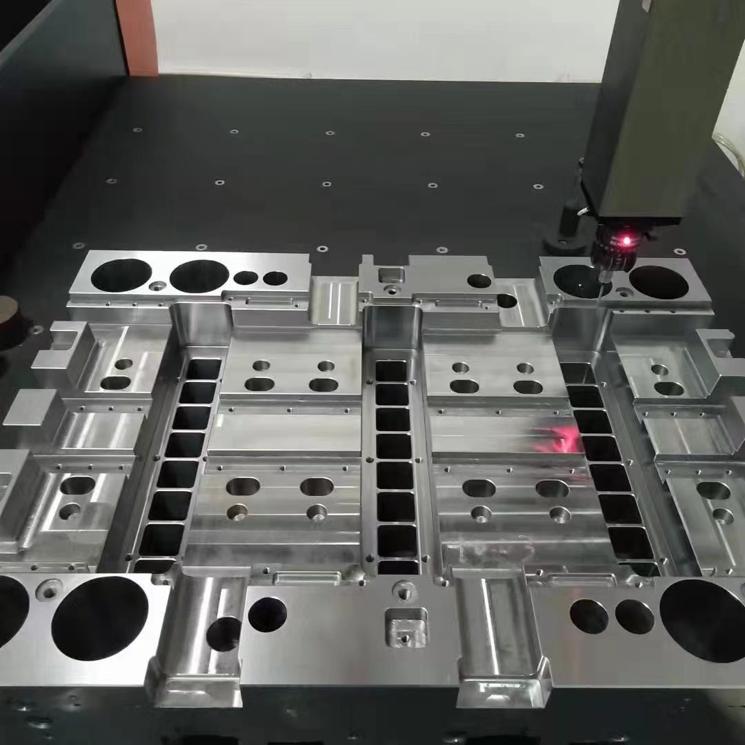
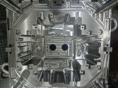
When I first got involved in the field of mold making, I often stumbled upon the question—what exactly is a standard mold base? In short, a die base serves as the fundamental structural platform in injection mold designs. Unlike the custom-machined mold inserts, die bases come with standardized dimensions, pre-milled pockets, and guiding components, significantly reducing design and machining time. As someone who's been deep diving into manufacturing optimization, trust me when I say that selecting the correct die base solution impacts everything from cost-efficiency to overall performance precision. So how does copper come into play here? We'll get there.
| Component Type | Typical Usage | Main Benefit |
|---|---|---|
| Conventional Tool Steel | Prolonged cycles, durability-demanding operations | Extremely durable, long wear resistance |
| Aluminum Alloy | Bench-top molding & lower heat environments | Economical but limits in precision and cooling |
| Copper Insert (e.g., P20 or C17200) | Hot working applications, quick heat dissipation zones | Highest thermal conductivity, ideal near cavity blocks |
- Increases heat removal efficiency during plastic melt solidification
- Lowers chances of sink marks in molded parts due to controlled cooling rate
- Enables high-tolerance geometries by minimizing uneven contraction phases
- Lowers stress points at insert-to-base connection lines over traditional steel
The Role of a Copper Block in Die Base Engineering
Moving on from basic terminology to materials—copper doesn’t typically come to mind when you think about die casting or mold engineering, unless of course your part is some high-heat sensitive electronic housing needing rapid extraction. Over the years I’ve used a variety of metals—from H13 tool steel all the way down alloy steels—nothing really rivals copper’s performance when you're battling hotspots in a core block area.
The block of copper, strategically inserted into aluminum or even beryllium-enhanced frames within a die base structure acts like a thermal siphon. I’ve observed its effectiveness not just via data, but practically—it literally drinks away localized heat where mold temperatures peak and creates more balance across mold surface areas, which is absolutely vital for tight tolerancing requirements in production molds. And don't underestimate weight; even though copper has a higher thermal transfer coefficient versus tungsten alloys or brass counterparts, you only use them where necessary.Main Applications:
- Copper-based ejection sleeves in ejector pin cavities.
- Inset into B-plate cores of progressive dies and hot-runner systems
- Fins integrated into cavity backs to radiate off trapped heat from runner gates
Cooper Grates in Cooling Solutions and Thermal Dissipation Areas
I must clarify upfront: no, Cooper Grate doesn't refer to some old plumbing system leftover from 1890s cast iron workshops—that's probably confusing “cooper" with "copper." But what is interesting about copper again lies deeper inside industrial jargon around ventilation slats or cooling structures in pressurized mold environments.
A Cooper grate essentially refers to specialized mesh-like plates fabricated usually using either copper alloy sheets (or sometimes bronze-infused grids) used inside mold base assemblies for improved airflow and moisture expulsion. Think of those little micro-channels embedded within the ejection unit—we found out in one project that they drastically prevented flash accumulation especially during multi-layer cycle runs where condensation tends to accumulate along the rear side between plate sections if humidity levels exceed tolerance ranges. These grates aren’t just aesthetic additions; these are functional features allowing both air and steam movement, particularly during automated shutdown procedures where residual heat still remains for a period post-cycle completion. TIP: When planning complex molds, I've learned that adding Cooper grate slots inside the support pillar area behind cavity plates improves ambient air circulation dramatically while keeping waterline routing simple, helping us avoid excessive drilling and potential seal issues down the line. ---How to Choose Between Standard vs. Modified Mold Base Units
Pros/Cons of Standard Versus Customized Base Units
| Metric / Factor | Standard Mold Base | Custom Base System |
|---|---|---|
| Drawing complexity | High initial setup but repeat fast iterations possible once built | No prior blueprinting required |
| Lead times | Faster delivery since manufactured globally as per MISUMI/D&M guidelines | Significantly slower |
| Maintenance ease | Pre-defined spare parts inventory | Unique parts require OEM specific tools |
| THERMAL OPTIMIZATIONS POTENTIAL | Varies - requires integration point adjustments | Potentially higher via bespoke material zoning |
Let me tell you—I spent nearly six month re-working legacy mold systems without clear standard documentation...that's when standard mold setups saved me big-time financially, because replacement was plug-and-play and downtime reduced considerably compared to modifying every internal component after minor crash-related distortion in the ejection zone happened mid-shift. ---
Cu Blocks as Inserts—Best Practices from Hands-On Experience
In my daily work I see engineers under-estimate importance of copper insertion into existing cavity support plates. One example comes to mind—a medical component project we worked on a year back where slight temperature variations were causing subtle flow imbalances. I suggested integrating **block of copper (UNS-T3 grade)** directly next to sprue bushing area and saw immediate improvement in part uniformity after just second batch run. What helped further was that we left enough shrinkage allowance—remember, even soft solders between Cu and surrounding steel mustn't expand too aggressively against hardened mold faces. Now let's look at the do's an' donts of copper-based integration in die base systems **Don’t Do This:** Embed full block in regions adjacent eject pins—they'll warp slightly when hot leading to clearance misalignment over time. Also avoid placing copper where sliding contact between A and B plate takes place; it will rub badly. **Must Do List**: Always test with dry-run cycle. Preheated blocks tend expand quickly, creating pressure gaps between shank fit holes. Best practice is counter-sink fitting into base with graphite thermal gaskets ensuring zero direct conduction loss while maintaining firm fixation. Additionally, whenever applying to a two-plate system ensure proper location pins between block mounting area and guide bushes. Even submicron shifts can mess up your cavity wall thickness consistency in precision gear-molding scenarios.
---The Long Tail: Answering “What is Standard Mould Base"?
So going back to basics, what exactly qualifies as a 'standard mold base’? Simply speaking, these ready-manufactured assemblies come with preset layouts for cavity positions, leader pins and bushings already set up following industry standards (usually conforming DME type-A, B, or P series or LKM specifications). You buy them from trusted global suppliers like Hasco, FUTABA or Strack—and assemble your mold around these fixed frame sets. That's why this choice makes a lot sense if speed, compatibility, and modularity top among concerns driving your product launch strategy. But here’s what few discuss—you need a balance between off-the-shelf simplicity and localized thermal challenges, such as when dealing with highly conductive resin compounds, which is becoming mainstream nowadays especially with aerospace thermoplastic resins. As a mold development engineer myself I've found value pairing a copper-based insert in strategic heat buildup locations within standard die bases—not only improves cooling dynamics, it gives you wiggle room for process tuning down the line. If there's one lesson my five+ years has taught me is never compromise rigidity just because you’re adding non-standard components. This philosophy works extremely well in large-scale automotive lighting mold units running upwards 40,000 shots a week. To sum this up: **Takeaway Points:**
- Die bases act as foundational support, critical for interchangeability and repeatability
- Add a block of copper in precise cooling problem spots for thermal balancing benefits
- “Cooper grate" terms refer to vent grid mechanisms that allow heat discharge paths
- A ‘standard mould base’ reduces fabrication efforts significantly through modular adaptability
- Copper enhances heat diffusion where other metals falter
Conclusion – Making Smarter Investments in Tooling Materials Today
To recap the core lessons from this detailed dive:
- If you care about speed, cost control, and dimensional consistency—stick with proven die base systems.
- You’ll gain massive advantage in cycle times by introducing thermal management strategies, most notably the application of targetedblocks of copper.
- If overlooked vapor build-up affects finish quality, exploring use case applications whereCooper gratingssolve real production bottlenecks should be considered early.
- For engineers looking towards lean manufacturing models and minimal downtime risk in production—the best route combines both the standardized approach while incorporating tailored copper insert placement in areas requiring dynamic thermoregulation.


