Does Copper Paper Effectively Block Drone Jammers?
When I initially came across copper paper, I was intrigued about what its practical uses might be. From what I could see at first, it appeared just as an oddly shaped piece of die base material that's often mistaken for just another decorative element or industrial scrap left lying around. But things took a turn when a discussion online brought to light something I hadn't thought about: can copper paper really act as a viable way of mitigating drone jammers?
For me personally, trying to work through this question involved testing a few assumptions I previously made, especially considering how modern electromagnetic interference (EMI) functions with small-scale drones and jamming devices used by both hobbyists and government operators alike.
Diving Into the Die Base Concept
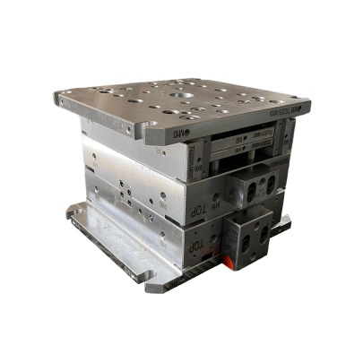
To properly assess copper paper’s role in drone signal blocking, one has to start looking more carefully into what exactly constitutes a "die base". Though the terminology here sounds overly industrial, it basically refers to a foundational template used across fabrication—particularly where metals are concerned.
My exploration into this field led me to examine different types of conductive foils like copper paper. This stuff is surprisingly affordable and quite flexible compared to rigid copper sheets. The idea being that it’s a thin yet durable option you'd use if creating DIY shields for EMI or similar applications.
The Physics Behind Blocking Signal Interference
- Copper’s conductivity: Being among nature's most efficient electrical conductors
- Jammer signal strength: Varies between personal-use and military models
- Foil thickness and coverage:直接影响屏蔽效能 Shielding performance hinges heavily on both physical size of the material and its layer depth
- Coupling with antenna resonance frequency range
Differences in Application Methods: From Die Bases to Full Wrapping
While exploring whether copper sheet works optimally for blocking, I found myself experimenting by simply laying sheets over small transponders or using a die-based trimming method that allowed partial shielding without excessive bulk. Others suggested "just wrap it up completely", which in practice isn't very elegant—though somewhat functional when working inside enclosed cases or boxes made from conductive polymers.
Why Use Base Trim Molding Techniques Instead
Eventually, as part of my experiments trying out alternatives, I stumbled upon base trim molding approaches involving aluminum-coated foam and plastic edges molded tightly along surfaces. It turned out this offered superior contact closure along seams which copper alone struggled with because the foil couldn't maintain continuity across complex shapes consistently. In terms of pure mechanical application flexibility? Base trim molding wins.
| Feature | Copper Foil (Standard) | Aluminum Base Trim Mold |
|---|---|---|
| Cost-effectiveness | + Affordable in large roll formats | Moderate cost per unit length |
| Rf Shielding Consistency | Inconsistent seam connectivity risk | Even coupling throughout structure edge |
| Installation Complexity | Potentially fussy placement | Easier pre-form fitment available |
| Lifetime durability | May bend easily; oxidation risk | Variably strong composites last better |
A Real-Field Test Setup I Built to Check Signal Resistance
Wanting concrete data beyond theoretical conjecture, I set up basic RF test conditions: placing two Raspberry Pi-controlled FPV rigs at varying angles—one attempting stable link maintenance, while simulating nearby noise interference akin to mild commercial-level jamming equipment (low wattage output). Covering receivers partially in different configurations:
- Tin-plated copper layers directly attached using conductive adhesive.
- Untreated sheet metal scraps laid atop surface gaps near receiver modules.
- No enclosure—pure open transmission trial setup.
Result? Surprinsgly modest attenuation with tinned copper versions offering minimal (<2 dBm difference), not enough to reliably suppress intentional disruption signals unless applied densely and folded repeatedly into multi-laminated forms—an inefficient approach if aiming to protect actual flight equipment routinely used outdoors without major redesign.
Towards Better Alternatives - Tin Coated Die Cast vs Solid Meshed Copper Boxes
During later attempts, a different solution caught my interest: how to tin plate copper properly? I found tutorials online discussing plating methods involving solder paste baths mixed wih flux mediums. This helped boost the already conductive foil layers with slight corrosion resistance and added structural firmness—a useful benefit since bending or cracking tends to degrade signal protection rapidly.
But let me clarify—I wouldn’t recommend amateur tinning setups. The precision required for consistent layer uniformity means even experienced technicians struggle to maintain reliability at home levels unless dealing only with non-critical electronics. Still, for certain niche use cases (like temporary sensor housings)? Definitely worthwhile.
Conclusion: So Does Copper Foil Really Block Jamming Signals Effectively?
Looking back after running countless variations and comparing them to real hardware enclosures using advanced molding and metallized fabrics… I honestly think plain copper sheet alone doesn’t live up to the full hype surrounding EMI jammer mitigation without extensive secondary support measures. Its advantages exist—but limitations around consistency, shape adaption, wear resilience, and sheer labor investment tend to stack fast unless your setup involves very stationary or indoor-only usage.
- If looking for simple solutions to counter light-frequency signal spoofing attempts → solderable copper film helps a little.
- If planning regular outdoor drone deployment under harsher EM environments → Invest wisely in composite casing options or pre-fabricated jam-resisting housings.
- Tinted / laminated copper papers worth pursuing for custom die-cut scenarios – just don't assume foolproof jam prevention alone.
- Always remember—no shielding works well without complete grounding and proper signal loop paths established!


