Copper Cathode vs. Die Base: Understanding Their Roles in Industrial Applications
I've worked with copper and molding for years — the learning curves are endless and nuanced. The key difference between a copper cathode and a die base lies in their primary functions and materials of application. In industrial environments like metallurgy and metal forming, understanding when and how to use either can impact the outcome significantly.
I want to take a technical but practical angle here because I’ve run into issues where misidentifying which material to go with cost time and labor. Let me walk you through my perspective and experiences with both elements — especially when they intersect during processes involving dissolving, plating, or molding operations.
Differentiating Die Base from Other Molding Terms
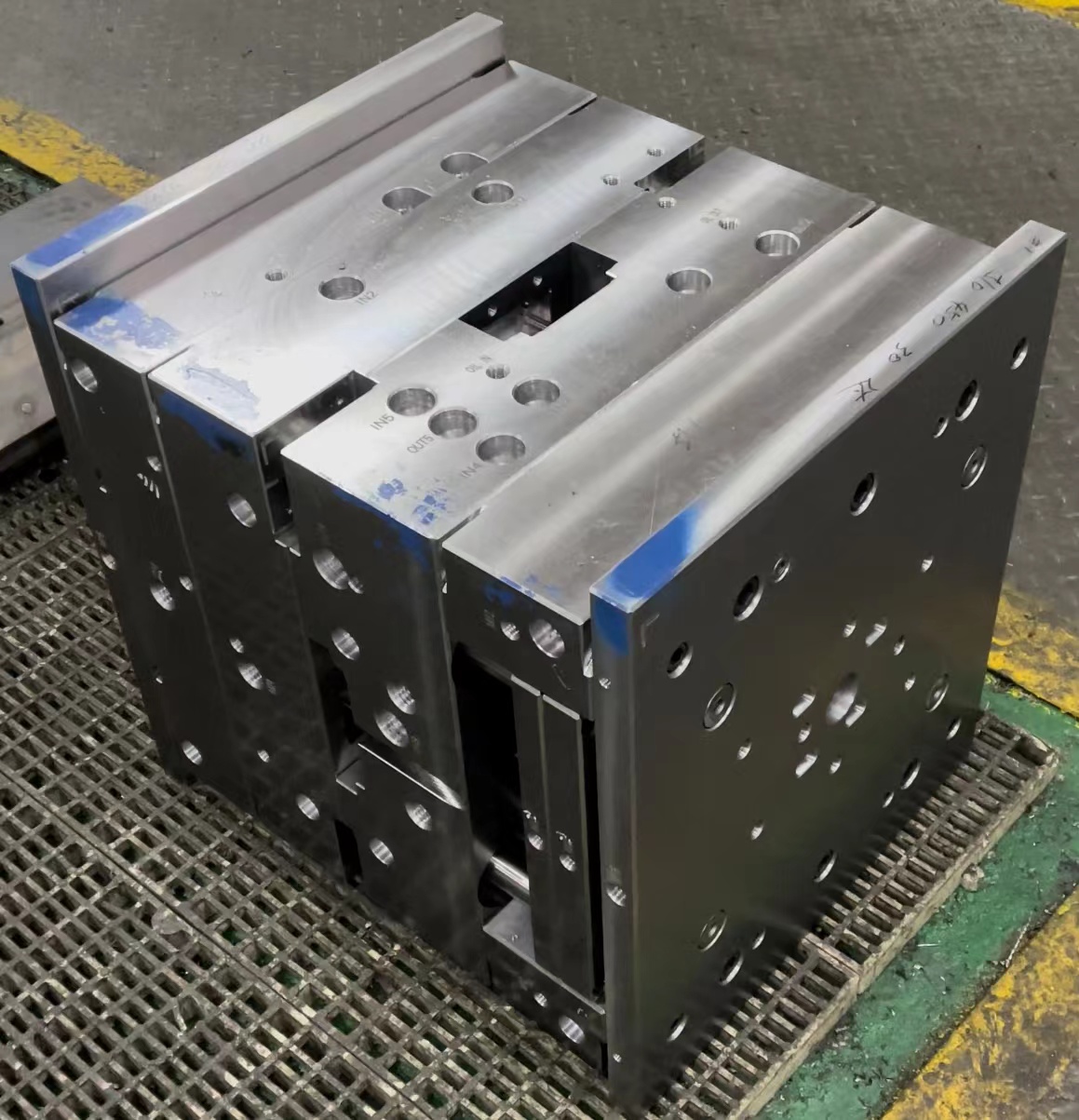
The term 'die base' is often mistaken for terms related like 'die insert,' but there’s an operational difference. From what I’ve seen over my career, a die base is simply the structural foundation on which a mold pattern — including cavity inserts, cores, and plates — sits. It’s essentially where the pressure builds. If it’s compromised, even by poor alignment during assembly, you're not just facing quality degradation — your tools might warp, or you may face premature wear due to stress concentrations.
- Used commonly in aluminum die-casting machines
- Manufactured typically from tool steels (H13 is my go-to)
- Provides dimensional stability when paired with hardened bushings and guides
- Should always include vent channels for gas release during filling stages
| Distinguishing Feature | Metal Type | Function | |
|---|---|---|---|
| Die Base | Tool Steel (often AISI H13 / P20) | Frame holding precision-insert mold blocks | Bearing Load and Retaining Inserts Under Pressure |
I find using a hardened steel backing plate underneath essential. This way, the clamping force stays distributed and doesn't crush any delicate areas near ejector housing pockets that aren't meant to bear such load.
The Significance of Base Molding Accuracy in Tool Assembly
The concept around 'base molding' goes hand-in-hand with the integrity of dies. What we’re talking about here is accuracy — if parts aren't aligned properly against the base block, you're introducing risk factors that show only after multiple cycles.
- Dimensional variance leads to warping or flash defects
- Tight fitting requires proper clearance and polishing at parting lines
- Sometimes thermal expansion has to be considered depending on alloy being casted
A mistake many newbies do — they ignore the fit-up before running trial shots, resulting in uneven cooling. Trust me — this costs time more than anything, as re-machining becomes the routine rather than exception.
Why Copper Cathode Holds Special Importance

In contrast, while working on high-conductivity copper applications, I learned early on not every type of raw copper stock qualifies as 'cathode-grade.'
So, what's copper cathode? Essentially, pure copper that has undergone electro-refining to strip off metallic impurities such as nickel and silver traces beyond desired tolerance limits, leaving behind >99.75% Cu content.
I've noticed a major problem arises during recycling where residual tin or cadmium alters casting temperatures. So whenever purchasing ingots for melting operations — particularly those aiming towards aerospace conductor extrusion—always ask whether the product is stamped as "Electrolytic Tough Pitch", also ETP, per standard EN AW-CR 88753/ISO 2159.
Removing Silver Plate from Copper: Real World Methods
In certain maintenance procedures where components need restoration — especially older terminals in substations — you're often faced with a common longtail question users have been asking: "how to remove silver plate from copper."
- Start with acetone wipe-down. Most contaminants are grease-based; this step prevents vapor reactions later on
- If thick coating layers exist: Use a sodium hydroxide (NaOH) bath heated to approx 90 degrees C for partial softening (approx 3 minutes immersion).
- Select one of two techniques depending on available facilities:
- Mechanical scraping — safer but less efficient, ideal if surface must stay untouched post-process
- Dip in a mild nitric acid solution for quick etch-off; make sure ventilation control exists.
Note: When dipping in nitric solutions (), I usually use protective glasses plus butyl glove under nitrile outer layer since splashes eat fabric like water does sugar cubes! Also — neutralizing with a diluted carbonate wash post-treatment ensures pH returns below discharge legal standards (pH=6.5-8.0), so environmental compliance checks easier downstream at plant waste processing tanks.

Here are several safety tips based on personal experience with plating removal:
- Rare earth particles sometimes cling tight — add some oxalic crystal dust if stubborn spots appear resistant to first treatment phase
- To preserve geometry integrity avoid blasting unless component shape remains non-critical
Beyond Materials: Application-Based Design Choices
You know the frustrating situations when choosing material boils down to context and not a fixed list? Sometimes I had no clue until third cycle why the ejection wasn't smooth — turned out I ignored the thermal behavior curve between die base steel alloy and molten metal viscosity coefficient at fill temperatures specific to zinc-aluminate mix. Oh yeah, small details matter when things heat up literally.
| Cycle Stages Involved | Critical Factors Impacting Output Quality |
|---|---|
| 1- Initial Insert Fit Check | Fine lapped faces prevent leak-off at joint interface leading flash issues. |
| Mold Heating Before Shot Start | Differing TEC (Thermal Expansion Coeff.) values of base structure metals cause differential expansion stress |
| Eject Pin Movement Over Time | Holes drilled oversized initially account for wear but must be checked periodically |
Copper Versus Die Base: Which Comes First?
The order of priority really depends where I sit during project design — if I was engineering a busbar array versus optimizing flow gates inside hot runner dies, I'd prioritize copper conductivity over die hardness ratings any day, but vice versa during injection cycle fatigue evaluation tasks.
- Ceramic encapsulation preferred with copper alloys to maintain thermal insulation without increasing electrical resistance beyond tolerance thresholds
- Steel base dies used in gravity die-casting setups perform better at lower temps due limited tool distortion under load — great pick for semi-permanent mold applications
- If I need maximum heat dissipation without compromising rigidity (e.g., EDM electrodes) — copper infused graphite wins despite its fragility concerns
Conclusion
My take is straightforward: You won't replace die base considerations when dealing with mechanical robustness needed across thousand shots in high-rate manufacturing setups—but if you overlook copper's critical role in high-frequency current systems, then you open floodgates for system overheating disasters. Balancing performance, cost longevity and ease of repair hinges on knowing when each deserves prominence.
Remember – never cut corners on preliminary tests even though time pressure mounts up! My best runs happened precisely because I slowed down to calibrate everything beforehand rather rushing straight into full batches. Hope sharing insights here could help someone save time next round,
Gabriel Nunez - Metal Process Engineer since 2005 🤠⚙️