
Copper Blocks for Mould Base: Enhance Your Injection Molding Efficiency
If your work relies heavily on injection moldind—whether for prototyping or high-volume production—you’ve likely experienced heat transfer inefficiencies, cooling line failures, or excessive tool wear that cuts into your cycle times and margins. My goal here is not to offer some generic solution from a sales page, but to share what I personally learned through countless iterations of trial and error—and finally, a real breakthrough: copper blocks for mould base applications.
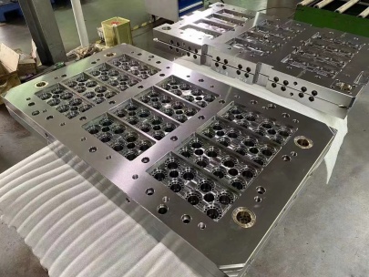
Understanding What Exactly Is a Mould Base
The **mould base** isn't just a frame. It’s the backbone of precision in injection molding setups, supporting inserts, guide bushes, ejector mechanisms—all while maintaining tolerance within fractions of an inch.
A solid foundation, one might say, but in more ways than metaphor. Over the years, I worked with P20 steel bases and aluminum alloyed support structures. Then came copper alloy insert cores—a subtle but profound shift in thermal conductivity and heat management.
| Material | Thermal Conductivity [W/m°C] |
|---|---|
| P20 Steel (Common Tool Grade) | ~35 |
| Aluminum (6082 Alloy) | ~160–200 |
| Copper Beryllium (High Performance Block) | >300 |
The Thermal Edge of Copper Blocks
Heat control is where most operations suffer the slow death by seconds—seconds you could recover every time a batch runs. And yes, copper is softer and heavier than standard steel or even many aluminum alloys I previously relied on. But when placed within a carefully machined pocket in the cavity retainer—or better yet, as part of a thermally isolated zone—it performs beyond anything my last CNC team had predicted.
You won’t get this performance by dropping any random block off your bench inventory. You'll need specialized machining and possibly plating. More importantly, you must integrate them with smart waterline placements. The result: fewer sink marks, lower stress in thick sections, improved fill pattern symmetry, shorter overall cooling cycle—even faster than adding baffles and bubbler systems.
- Faster heat dissipation due to higher W/m°C value
- Dramatically improves cycle efficiency per cavity
- Lasts longer with correct coating & design support
TIP: Not sure which grade? Go withBeryllium Copper 25 (UNS C17200)—temper hardened, aged. Yes, cost increases, but consider it process insurance against fatigue.
Vinyl Cove Base Molding Isn’t Far Away
Honestly, the first time I used this term “Vinyl Cove Base Molding" came during cross-department brainstorming. That day, we were looking at architectural profiles and thinking about wall transitions. While far outside our main mold manufacturing context—I’ll admit—the idea made perfect sense for micro-channel routing in a compact mold plate stack-up.
We tried applying this same concept into the side channels for ejector pin lubricants and air vent pathways. Think of V-shaped reliefs along mounting plates: no sharp edges, smoother flow paths. We found it reduced turbulence around coolant exits. Don’t be fooled—these weren't aesthetics plays—they actually increased system life.
The take-home point was clear. Innovation sometimes starts outside core domain—like interior finishers talking shop—and makes an accidental appearance on your blueprint sheet tomorrow.
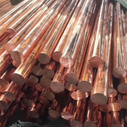
Selecting and Cutting Your Copper Plate – How to Approach?
The big question comes down to this "how to cut copper plate." For starters: don't think of using the same cutting tools for H13 steels and expect clean breaks in beryllium alloys!
- Use ultra-high-precision CNC water-jet cuts for profile roughing if possible.
- Polishing with diamond pastes works better for achieving mirror finishes without damaging surface integrity post-machining.
To sum this section concisely: poor edge preparation = poor cooling response later. I've seen copper block misfits create localized stress points under injection shear load that ruined weeks’ worth of build-up.
- I typically follow these cutting best-practices for copper blocks:
- Apply lubricant consistently but never excessively—copper likes to retain friction-generated heat, leading to tool glazing.
- Run milling bits slower, especially for thicker blocks (>5 cm), otherwise burrs form.
- If hand sanding required after, use progressively finer abrasive sheets instead of grinding too aggressively—especially if near mating face zones.
Retrofitting Old Mold Sets? Here's a Reality Check
If upgrading an existing mold, forget retrofit kits claiming instant insertion compatibility—chances are the internal alignment will cause uneven heat dispersal. Unless done properly, retrofitted copper might behave like cold glue stuck over cracks. I’ve been there.
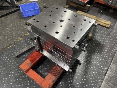
Mold retrofit steps: - Measure existing ejector pin depth tolerance. - Assess base clearance between moving plate supports; adjust accordingly before placing copper inserts. - Ensure proper epoxy bond strength for non-interference mounted sections if adhesion necessary.
Don’t force fit unless all angles align—otherwise you risk creating stress lines at the block/tool interface, which may only appear days or dozens of cycles later during a press check routine.
One trick: If I can't afford total remachining but still prefer a copper component—I try integrating smaller, segmented heat pipes instead. These function similarly—just different packaging!
Remember: Copper doesn't compensate poor planning; it amplifies good prep ten-fold.
Economics and ROI: Is It Just Hype?
| Factor | Type A Mold (Without Copper Blocks) | Type B Mold (Copper-Integrated Version) |
|---|---|---|
| Avg Cooling Cycle Duration | 48 sec | 40.5 sec |
| Projected Mold Life | 420,000 Shots | +/- 598,000 Shots |
| Tool Cost Difference Initial Outlay | - | +$31k (est) |
| ROI Timeline (Assumed Daily Useage - ~5 batches x 2K Units)' | — | Under 11 Months |
Towards Real Gains Through Smart Material Pairing
If anything has become clearer over years working alongside tool makers and simulation teams, it’s this—if there's one element we should revisit seriously it’s how thermal dynamics in molds influence yield quality, waste margin, machine longevity, and downstream assembly ease—across sectors ranging from medical device casing to consumer appliance shells.
Final Thoughts
In short, copper blocks in the **mould base area** have reshaped parts of my workflow. They are not replacements—they enhance rather than replace. However they demand respect when selecting, sizing, and setting in place.
- Beryllium-Cu alloy offers top-tier conductive qualities.
- Proper placement beats material cost optimization hands down.
- Use 'Vinyl Cove' type reliefs for smarter coolant exit geometry in some designs.
- Sacrificial blocks help preserve other structural members longer over repeated shifts. If you ever struggled figuring "How to cut copper plate", now would be the time to master tooling parameters—because poor cuts lead to poor thermal contact.
- Achieve measurable reductions in shot cycle timings once optimized for copper-enhanced zones.