
Does Copper Block EMF and How Does This Affect My Work With Die Base Technology?
I’ll be frank right up from the get go—I’m someone who works with die base systems a lot. Whether we're designing them, modifying them, or just trying to make sure their environments don’t kill signal stability, there comes a time when electromagnetic interference (EMF) becomes a massive thorn. I know you’re asking this question because like me, you probably encountered an unexpected signal glitch, maybe even overheating in your die base housing, and now you're wondering—does copper really stop that noise?

What Exactly is Electromagnetic Interference and Why Is It Important?
First things first—if I want to answer does copper block emf in my situation then understanding EMF itself becomes necessary foundation before jumping in blind.
Electromagnetic Interference (EMI): Disturbance in electronics circuits generated through electromagnetic fields caused by man made or natural phenomenon like electric engines or solar radiations which leads to circuit misbehaving or performance deviation issues especially relevant to precision tools involved within die-base technology applications including sensor readings calibration and heater block functions like those seen using ‘copper heater blocks'
- Magnetic component from AC lines causing voltage fluctuation near microchips
- Cutting tools nearby induction generators emitting pulsed fields
- Die-based equipment operating at high frequency leading internal interference loop
- Cause erratic behaviors in analog & digital sensors
- Reduce accuracy levels during real time feedbacks used for die mold pressure measurement
💡 Key takeaway about EMI impact:
| Source Type | Impact on Die Base | Solutions via EM Shielding Application |
|---|---|---|
| Metal-Cut CNC Tool Motors | Sensor jitter + false triggers from Hall devices inside die frame modules | Fabricate copper lining across casing interior to prevent coupling |
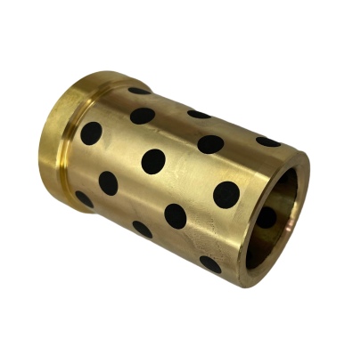
| Infrared Heaters (Proximity to Die Core) | Temperature instability within thermocouple regulated copper heating unit (heater block), risking melting alloy joints prematurely | Shield copper heating blocks using thin layer aluminum foil + magnetic flux rings around core elements |
The Physics of Copper – Why Use It In First Place?
When it come too shielding copper is no casual candidate thrown onto shield material lists randomly—it’s scientifically grounded why engineers turn back oftenly again & again while tackling radiation leaks. Let’s quickly breakdown few key physical traits making Cu a popular choice.- Copper possess excellent electrical conductivity — allows dissipation path for EMFs effectively without building standing wave harmonics that might interfere elsewhere
- Good absorption rate across radiofrequency ranges, meaning less reflection based energy bounce between adjacent un-grounded materials found within die bases
Critiquing Other Options Verses Pure Metallic Solutions like Silver Or Gold Plated Ones...
Some folks say pure silver offers best possible conduction—but unless budget has infinite space (like if NASA was doing research here) it's unreasonable to apply for die bases where cost scaling and repeatability is needed. On gold, same reasoning applies. Instead what usually occurs practically? Coppers gets **coated** either through: - tin dipping - Nickel overlay layers over raw sheet copper All aimed for better surface preservation yet maintain original shielding behavior intact without degrading overtime. So conclusion? Even after considering other alternatives copper still holds prime position for practical engineering purposes involving die base shielding implementations especially those requiring regular heat exchange such copper heater assembly unitsPractical Steps – Making Copper Blocks At Industrial Shop
Maybe some users out they actually need step-by-step on how to build copper blocks manually? Here are several stages typically undertaken when fabricating one for custom shielding needs involving machine parts associated wuth “die base". Note that process below reflects general manufacturing approach used commonly not lab tested nano scale purity techniques! Step by Step guide:- Pick correct Copper Grade e.g.: OFHC (oxygen free high copper ): Min 99.8 percent pure Cu—better RF attenuation
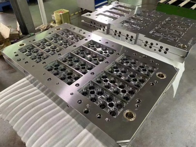
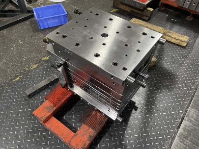
- Using CNC milling setup—cut rectangular block into pre-determined size dimensions matching intended application fit into mold frames or around electronic sub components prone to pick noise
- Surface finishing using polishing past followed light lapping procedure
| Material Used | Machining Process Type | Ease Of Manufacturing |
| C103 (Low impurity electrolytic Copper Rod stock) | Laser cut+grinding hybrid approach | Advanced skill required—may risk distortion if temp controlled incorrectly |
| American standard 16 oz per sq ft gauge copper foils | Custom stamp press cutting for simple shaped shielding covers only | Easier, faster batch fabrication method |