
In my line of work — machining custom parts and producing molds for various industrial clients — one aspect remains critically underrated: choosing the right base for a mold that ensures long-term reliability and production integrity. That base is more than just a physical structure — it’s your foundation in literal and figurative terms.
The Anatomy of a High-Quality Mould Base
I don’t think most people realize just how engineered a proper mold base needs to be until they've seen their own system buckle under thermal expansion inconsistencies or material defects.
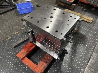
Firstly, a high-quality mold base is typically composed of standardized templates and guide components that serve as structural platforms for injection molding. Common materials for this include SKD61 alloy steels (P20 pre-hardened tool steels) which are durable enough to maintain rigidity but also easy to machine. It houses ejector systems, cores, cavities — anything necessary in the molding phase — but must remain consistent in form even during high-temperature operations.
| Component | Purpose | Material Suggested |
|---|---|---|
| A/B Plate | Distributive flow channel; cavity positioning | P20 Steel |
| Ejector Box | Ejection sequence control | Carbon Steel (Hardened & Tempered) |
| Bushing/Leader Bushing Set | Precision alignment mechanism between halves | Titanium Nitride-Coated |
| Ejector Pin Housing Block | Holds guiding pins; facilitates ejection stroke | D2 or HPM38 Alloy |
| Footing | Benchmark level contact points for stability | Annealed Tool Steel Base |
How Material Quality Affects Performance
Let me tell you something from first-hand experience — poor-quality Copper Cathode doesn't just degrade conductivity rates but messes with the overall heat retention capabilities in electrical discharge machining setups.
- Use only Grade A copper when manufacturing core pin molds.
- Oxygen-free variants ensure longer wear on EDM-cut surfaces.
- Mismatched alloys lead to micro-fracturing over repeated exposure.
- If your supplier ships “low-purity recycled cathodes," expect uneven wear and pitted channels.
You need the cleanest current paths in EDM applications to avoid dimensional drift over thousands of cycles. And here’s what no marketing pitch will warn you — if you cut corners by selecting low-torque-grade Copper Cathodes thinking they “save a few cents per run", you’ll pay back every dime in rejected batches and post-process hand-finishing later on.
Copper Grates as Conductive Support Structures
In many precision cooling configurations, I’ve started using what's commonly labeled an under-table “copper grate". Most manufacturers aren’t even considering these things when planning coolant management. But I have used them to:
- Rapid heat dissipation through layered copper matrix grids inside water lines,
- Reinforce edge rigidity without adding significant mass or altering CTE mismatch between plates,
- Create electromagnetic isolation zones where high amperage fields would interfere with signal-based monitoring equipment mounted near presses.
They’re a game-changer for complex multi-cavity tooling setups because of how finely controlled thermodynamics can be with proper copper grates. Just make sure that whatever grade you use isn't going to leach other trace compounds into adjacent metal zones during tempering cycles — it creates all kinds of bonding anomalies downrange at the interface points.
The Practical Challenge in Measuring Base Moldings
If you’ve ever asked yourself 'how to measure and cut base moulding', then welcome to the club I never wanted to join. It's not intuitive, unless someone shows you a systematic workflow.
Here’s what happens in practice before we break down steps. The mold isn’t just aligned horizontally — especially when stacking multiple layers like those in tandem cold chamber machines — so standard laser measurements often give incorrect offsets due to refractive index variation from steam exposure around hot runner blocks.
- Laser calibration must compensate for ambient temperature changes between AM and PM readings
- Clamps should be preloaded according to specified torque tolerances prior to digital scan registration
- Thermal cameras reveal warping tendencies after cutting profiles, but before assembly begins
| Tool Used | Typical Tolerance Rating | Purpose of Tooling |
|---|---|---|
| LMI-94 Laser Micro-Interferometer | +./-005" | Spatial mapping and gap measurement prior to insert fitting |
| Jawz Digital Caliper | .+/-0.02mm | Detect internal chamfer mismatches post-casing milling |
Common Measurement Mistakes to Avoid
When attempting **“how to measure and cut base moulding"** there are classic pitfalls that seem obvious once you’ve ruined three trial bases trying different calibrations. These issues include assuming flatness when it’s not guaranteed, or relying strictly on linear gauge specs in humid shop conditions.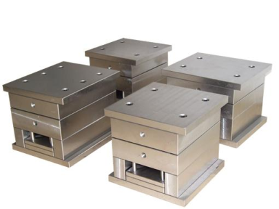
For starters — you should check whether your steel stock wasn't bowed or improperly cooled during its final treatment cycle before measuring starts happening at all. Otherwise you could be making perfect math adjustments on bad assumptions and wind up wasting hours chasing phantom fits and false clearances.
The Impact of Precision Engineering On Product Lifecycle
If everything checks out — base fitment is spot-on, copper cathodes used meet ultra-high standards, and copper grates allow efficient cooling paths while reducing localized deformation — what do you really gain? Not much… just longer-lasting product quality and tighter process controls. But honestly, I see shops running two extra weeks before needing tooling service because they built the damn molds better.We talk about efficiency a lot in production discussions, but what truly matters longterm is sustainability. Your customers get cleaner cuts, repeat orders don't end in inspection delays from inconsistent gate flash lines — and your floor teams feel confident in starting cycles fast because tools just "click". That kind of intangible operational rhythm pays off way more reliably over quarters than any cost-cutting shortlist might otherwise suggest. So, investing in quality mold bases and related subsystem components shouldn’t be treated like discretionary overhead, it is an ROI accelerator for future output capacity.