
What Exactly Is a Die Base, and How Does It Compare to a Copper Plate?
In metalworking, especially in mold making and tooling industries, the terminology surrounding die components can get quite confusing. As someone who has spent over a decade navigating punch press systems and injection molds, I’ve often been asked about the difference between a die base and a copper plate—so lets unpack it.
I recall working on my first precision mold at a small manufacturing facility. A fellow engineer handed me a block of steel labeled “standard die base assembly," followed by some rectangular copper sheets, which were labeled as “1oz copper." I stared for a few seconds, trying to make sense of the application each had—and honestly? I got a bit turned around.
Die Base: More Than Just Steel Blocks
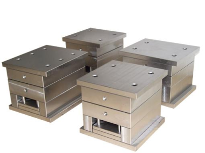
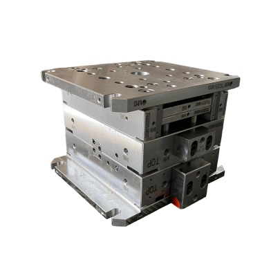
The die base is essentially a foundation structure used in progressive stamping dies and mold assemblies, primarily constructed out of hardened or tool steel. This component anchors other moving parts like punches, guides, bushings—and even supports the overall weight and stress of repeated cycling.
I always thought about it as the structural spine in the entire operation. Without an adequate setup here—things tend to break. And believe me, from personal experience, replacing broken dies at ungodly o'clock hours while under production schedule crunches feels about as fun as getting sand in your boot on beach trip that wasn’t well thought through.
| Attribute | Copper Plate | Standard Die Base Material |
|---|---|---|
| Material | Pure/Alloyed Copper | Carbon or Tool Grade Steel |
| Application | Heat Transfer, EDM electrodes | Mold framework, mounting support |
| Conductivity | High Thermal Conductivity | Thermal Resistant (Lower conductivity than Cu) |
Role of Copper Plates in Precision Tooling
So if die bases handle foundational mechanics, what do **copper plates** offer that’s worth using in manufacturing?
- They're typically used for EDM cutting where detailed profiling occurs.
- High conductivity ensures efficient energy usage during erosion processes.
- Easier shaping into custom shapes needed during complex cavity work (I remember how easy they were to mill back when our shop upgraded equipment).
A commonly seen term you may encounter related to these metals—particularly within circuitry or printed PCB boards—is "1oz copper". But this term specifically refers to electro-deposited coatings measuring a certain weight over an area—usually 0.0348 inches (~0.884mm). Not something you’ll ever confuse with a traditional die support unless mislabelled and left near your workspace during midnight shift chaos again...
Installation Considerations for Mold Cap Systems
This segues into one topic I still reference when mentoring younger fabricators: proper "how to install base cap moulding." While seemingly straightforward—or maybe irrelevant in context—it does come up often in mold casings and edge sealing procedures when creating multi-part tool systems.
- Start by dry-fitting all sections together before final placement.
- Check squareness along all four angles, particularly near ejection points where misalignment can cause sticking or wear unevenness.
- Tack-weld caps if required for stability—though in more precise setups like plastic molds, adhesive bonding works better with less deformation issues.
- Near finishing, apply lubricant along contact edges (a mistake I made earlier was skipping grease, which resulted in minor scoring we then fixed later via lapping... not fun on schedule delays.)
When Do You Really Need To Prioritize Between the Two
The core takeaway is simple enough but needs understanding: Use copper when dealing directly in EDM processes or heat dissipation is needed. The copper isn't structual. Meanwhile diebases? They form critical mechanical backbone. Don't confuse one with another no mater the material thickness, shape, label etc.
- Diebase applications require rigidity, shock load management
- Copper is only structural within specific electrical or cooling-based environments—not in heavy mechanical structures like molding units
Cutting Edge: Key Technical Insights From Practical Scenarios
Here are several real-life takeaways I learned working hands-on across mold design departments:- Avoid substituting 1OZ copper in places that require structural reinforcement—you'll just end up compromising dimensional accuracy due to miscalculations of thermal expansion coefficients and strength tolerance values.
- You'll frequently see “how to install base cap molding" referenced when designing plastic-injected enclosures with internal part locking mechanisms. Ensuring correct pressure seal at joint interfaces starts with perfect fitting molding installation—which again is more mechanical carpentry work than metalworking expertise per se—but overlaps occasionally with larger industrial mold integration projects.
Differences Worth Reiterating One Last Time
Key Notes:
- The term 'Copper Plate' refers mostly to thermally conductive elements; never structural load carriers.
- ‘Die Bases’ provide structural integrity but are typically insulated against temperature shifts since high conductivity here = disaster for wear lifespan.
- You might occasionally find ‘base cap molding’ installed alongside copper-based heat-diffusing elements—but that's situational in high-volume, long-run cycle scenarios, not general practice.
Final Thoughts On Selecting Correct Materials In Advanced Metal Applications
If there’s anything I've picked-up consistently through years of troubleshooting mislabeled inventory shipments and late-stage production failures: materials don’t care how cool they sound—they have functions best suited for individual roles.
Copper plates perform incredibly well in electric discharge machining (EDM), yes. Yet they’ll bow, twist, and literally melt if you try mounting punch inserts off them—unless its thin-section prototype stuff (which doesn’t last too far past R&D phase without upgrades anyway).
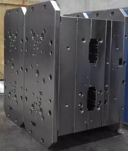
As for “die bases," treat those pieces with reverence. Those little numbered stamped blocks bear immense stress loads daily and should be built precisely to withstand the rigors of thousands—if not hundreds of thousands of hits across continuous manufacturing lines. Treat them like disposable? Expect frequent rework—and nobody wants that on weekends when beer’s cold and machine downtime isn’t.
To wrap it up simply—know when and where you apply either. Respect their functional boundaries, keep labels clearly visible (from personal experience, this really helps avoid mistakes mid-shift chaos) and don’t forget the role of things like installing base-cap-mouldings properly. These nuances matter in precision engineering and will differentiate average work from elite output.