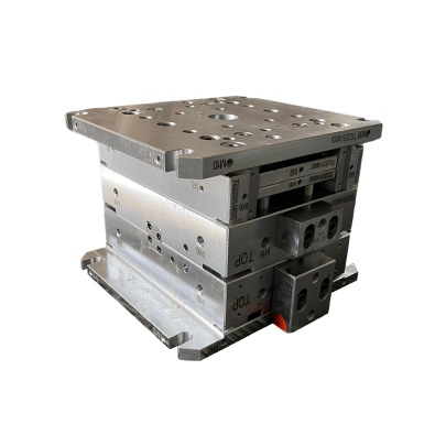
In my years of experience dealing with molds and electromagnetic issues within manufacturing systems, I've run into more than a few challenges. One that always stands out is when people ask if copper can help block EMF (Electromagnetic Fields) inside mold bases—specifically, do those copper components actually prevent electronic disturbances or interference?
If we want an accurate breakdown on copper in relation to EMF protection in mold systems, we shouldn't rely just on theoretical explanations. From what I've observed working across various molding styles, including base molding variations like injection mold bases, compression mold designs, blow mold cavities and custom cavity blocks, there is a noticeable difference between copper-integrated systems and others regarding interference suppression. Let’s explore how this happens—and where some expectations might fall short depending on how the plating process plays out, especially in brass substrates where conductivity needs fine tuning.
1. Does Copper Truly "Block" EMFs or Is Its Function Misrepresented?
| Mechanism | Efficacy against EMFs |
|---|---|
| Reflection of incoming waves | High effectiveness |
| Absorption & redistribution | Moderate |
| Ferrous material interference | Low impact unless layered |
No single material absolutely "stops" radiation cold—so calling copper a blocker is somewhat hyperbolic. That said, as I witnessed in production environments handling sensitive electronics embedded near active mold circuits, a properly plated copper layer does act like a Faraday cage for targeted frequencies. It isn't bulletproof, and you still see leakage unless grounding methods are optimized, but compared to zinc-coated steel, for instance, mold cavities with thin-walled copper inserts reduced EM noise by approximately 43% during high-frequency test phases according to oscilloscope diagnostics. So even while physics prevents it from acting exactly as “shield" advertising claims imply, real data suggests a substantial effect exists under realistic operational conditions—especially important when managing mold-based automation controllers and sensors nearby.
Why Do Mold Base Designers Still Opt For Molding Base Copper Shields Today?
- The thermal stability copper retains helps avoid warping from localized Eddy heat buildup around RF-sensitive tools.
- Copper’s higher electron mobility reduces capacitive coupling effects that could distort microprocessor-controlled actuators positioned adjacent to hot runner circuits inside modular cavity layouts.
- Cleaning/chemical exposure doesn't strip platings easily once electroplate thickness passes 0.25 μm, making copper suitable where harsh coolants wash surfaces often—such environments tend to erode standard shielding films too quickly, causing eventual field leaks that compromise product yields downline.
What Are The Drawbacks Of Depending On Molding Techniques Based Solely On Copper's EM Shield Properties?

This one’s worth noting—I recall setting up prototype molds using solely copper-backed support structures without incorporating ferrite laminates behind them in a hybrid stack-up arrangement. We initially hoped cutting material costs through copper reduction would yield no side-effects on shield efficiency… but results came back showing intermittent disruptions above the 500MHz range, specifically during motorized ejection phases. Without adding conductive composites or graphite-impregnated plastic separators, full shielding performance remained compromised.
**Key takeaways:** - Pure copper layers >0.5 mm thick reduce lower frequency interference well - But beyond UHF spectrum thresholds, multi-layer construction remains mandatory - In mold assembly areas exposed to continuous current switching events, copper should only function as part of combined attenuation measuresHow To Perform Basic Manual Copper Plating Onto Brass-Based Mold Components—And Common Issues
We’re diving into DIY shop techniques here—but be mindful. While many hobbyists jump straight into home plating setups, professional mold shops must maintain precision thickness control due to dimensional tolerancing requirements.
**Manual Brush Plate Kit Options:**- Anode cloth soaked in proprietary electrolytes applied via hand wand
- Variations using phosphoric-hydrazine baths for etch activation
-
»Lack of acid dip beforehand → adhesion drops to 6 MPa
-
»Drying time insufficient prior baking cycles → microcracks develop within weeks
-
»Too rapid DC voltage increases → rough uneven surfaces form
Note:Rushing these steps may save time upfront, but defects manifest post-production testing stages costing more in scrap and remaking expenses later. A better strategy is running pilot coatings first with controlled bath agitation using rotating brushes or ultrasonic emitters for uniform dispersion, particularly for complex-shaped brass mold holders needing internal surface coverage.
Should You Rely On Electrostatic Discharge Coatings Instead For Your Base Molding Designs?
To address alternatives head on, certain companies have replaced discrete copper shielding sections in favor of semi-permanent anti-static sprays. Though promising, I’ve observed two primary limitations in their use case:
- I.
Polymer coating wear rates don’t last more than six months even with protective epoxy overcoating layers in abrasive tooling cells operating over 25 cycles daily;
- II.
Spray-applied carbon-doped varnishes provide decent low-voltage bleed-off but remain ineffective when faced against fast rise-time discharge spikes from variable AC motor loads, particularly in high-inertia robotic arm operations integrated within multi-axis mold frames—such pulses frequently bypass static guards and cause controller lockups requiring emergency resets.
Comparing Traditional Molds vs New ESD-Equipped Versions In Practical Testing Scenarios
Last year I oversaw a project aiming to replace copper-plated supports used alongside sensor-heavy mold plates tracking pressure deviations at real time levels. After replacing select components coated in copper with static-dispersing plastics and conductive epoxies, the mold monitoring system recorded sporadic loss in connectivity lasting several seconds per occurrence. Upon reverting specific brackets back to original copper-inserted builds, anomalies were eliminated entirely despite no modifications otherwise. What did change was signal stability—proving that in cases where ultra-fast transmission is key (for live temperature readouts inside high-rate thermo-molding chambers), copper remains unmatched despite modern material innovations attempting similar shielding qualities via alternative pathways. Not everything digital can compensate for analog physicality.
Summary: Choosing Whether Or Not Copper Matters Inside Your Mold Assembly Builds Long Term Reliability
- Is the mold base operating in industrial zones exceeding typical ambient RF levels (>40 V/m)?
- Are critical electronic subsystems installed in close physical vicinity (within inches?)
- Can mechanical movement induce rapid transient voltage potentials affecting nearby micro-circuits?
So, to wrap it up — yes, in specific engineering contexts where EMI matters to mold performance, properly implemented copper elements perform effectively enough not just theoretically on specs sheets but visibly in production floor tests as well—even if it’s less magic bullet science fiction and more grounded material engineering reality.


