
Copper Block for Mold Base – Enhanced Cooling Efficiency and Performance in Injection Molding
When I first started working with mold bases, the cooling aspect always bugged me. Sure, standard steel setups worked — but they felt more like an afterthought than part of a precise thermal equation.
Then I heard about integrating a copper block within mold base assemblies. The idea stuck in my head, mostly because it promised better heat transfer rates compared to traditional materials used in core mold manufacturing practices.
This article shares my experiences and technical findings using a copper insert specifically designed for mold applications — not as theory, but as a real-life journey into performance improvement and cycle optimization during complex molding jobs that also touch into base trim molding.
Cooling Challenges in Mold Manufacturing
Anyone in high-output injection molding understands the nightmare scenario: hot spots near cavity surfaces cause delays in cooling time, inconsistent quality runs, and wasted man-hours chasing elusive process windows.
| Material Type | Metal Grade Commonly Used | Btu/(hr·ft·°F) | Cycling Impact |
|---|---|---|---|
| Steel Mold Base Core | AISI P20 | ≈ 16 – 19 | Slight Heat Retention, Slower |
| Copper Block | CDA-110 / C18000 Alloy Blend | 235+ | Faster Dissipation Possible |
- Prolonged heat dwell affects ejection clearance and warpage issues.
- Uneven thermal gradients can ruin cosmetic tolerances.
- Damaging effects on precision inserts increase tool downtime drastically if cooling isn't properly maintained across copper plated parts.
Copper’s Thermal Advantage Inside Mold Design
So why does copper even have space here among other more traditional alloy components?
Copper has nearly five times higher thermal conductivity than P20 tool steel. It's also less sensitive to thermal fatigue cracks when applied strategically within the water-cooling channels of complex mold base systems.
The trick, though — and this took me months of trial builds and CAD revisions to understand — is in placing the copper correctly around critical geometry points where localized overheating happens regularly. Areas where standard cooling lines barely scratch the surface of maintaining thermal balance.
This is why a copper-injected core design doesn’t just improve efficiency; done right, it reshapes the whole cooling equation. Think fewer scrap losses from uneven temperature fields, faster overall cooling without risking part distortion or premature shrink issues.
Key Cooling Benefits:
✔ Reduced cycle time (by as much as 12-25%)
✔ Lower resin shrink variability due to even temperatures
✔ Minimized risk of burn defects inside mold walls or ribs.
Choosing the Right Copper Alloy For Longevity and Conductivity
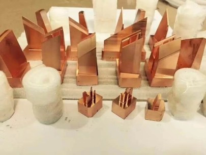
I’ve worked with two major copper alloy variants commonly marketed as options for mold enhancement inserts and internal flow zones:
- Oxyfree High-Conductivity Copper: Usually rated over .97 purity (electrolytic toughness grade). Known for extreme ductility and minimal oxidation in enclosed environments.
- Chrome-Zirconium Copper Alloys: This one surprised the hell outta me at first since some folks said the cost wasn’t worth the upgrade. Turns out? When exposed to frequent cycles of rapid heat/rapid cooldown, these alloys don’t lose their tensile integrity the way softer pure coppers do.
I initially went full soft pure copper thinking it was ideal due to higher TC — until one test block developed micro-pitting along its contact faces by week two.
| Electrolytic Pure Copper | Chromium Zirconium Blend | |
|---|---|---|
| Cost Factor | $$$ Cheaper | $ Higher |
| Cycle Stability | Okay | Much More Durable |
| Tarnish Risk w/Water Contact Exposure Over Months | Potentially Yes – detrimental to finish) | Lesser Reaction |
If you are running thousands of shots a week without consistent maintenance check intervals, don't skimp here. The durability trade-off really matters. Trust me, replacing inserts mid-job feels worse than reprogramming a CNC with bad tooling offsets.
Tips For Maintaining Performance – Preventing Copper Plated Corrosion & Issues in Real Environments
You know the nagging question many people ask online: does copper plated tarnish occur in actual shop conditions during prolonged operations? Short Answer: Absolutely, yes — depending on the humidity, chemical makeup of your coolant fluids, and general airflow around your molding bay area.
Trouble Zones Where Tarnishing Is Most Noticeable
- Rounded waterline bends exposed to stagnant water pockets overnight shutdowns
- Unventilated chamber cavities — common especially in larger mold blocks left idle beyond a couple shifts without drying protocols.
- Lubrication contact regions where grease mix reacts poorly with exposed copper edges (causing galvanic spots).
I had one mold that looked like someone had left old coins in saltwater by week six of run production.
In hindsight, adding corrosion-resistant epoxy barriers during build time prevented future headaches without compromising performance. Sometimes prevention wins long term, not material brute force.
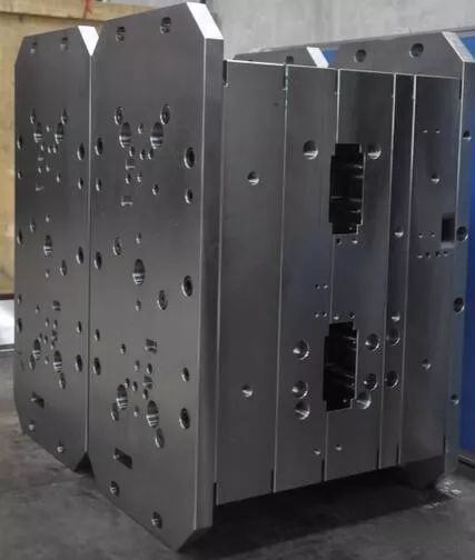
How I Integrated the Copper Into the Standardized Mold Base Frame Designs
This took a bit of trial, error — plus more collaboration with our machinist teams than usual — but here’s how it shook out after three separate mold redesign iterations and several dozen hours of simulation analysis:
First step involved identifying high-stress areas based on thermography scans during initial pilot tests. These “problem nodes" became candidate sites for inserting copper-based cooling structures instead of traditional drill-through tubing routes.
To maintain mechanical alignment and ensure compatibility during automated mold transfers or clamp changes, each block received laser-markings that helped track assembly sequence precisely during installation and later rebuilds.
- Use digital mockup platforms like Moldflow before physical testing phases whenever possible.
- Map predicted cooling curves via mesh models tied directly to mold stress simulations using imported product thickness profiles (this avoids guesswork later when tuning process parameters).
- Coordinate copper placement to avoid overlapping structural support zones. Keep cooling concentrated on cavity-heavy segments and gate entry paths.
- If integrating copper inside mold slides, always check motion interference using dry cycle simulations — don’t skip this! Some copper forms create odd collision patterns unless accounted early enough during setup stage.
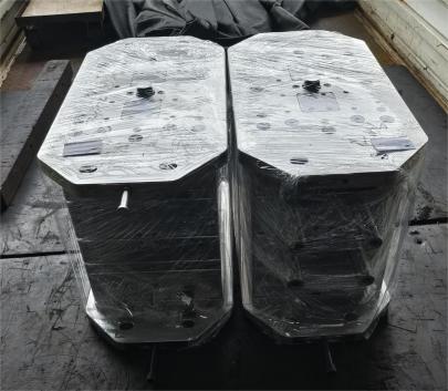
| Tech Stage | Description |
|---|---|
| Day 1 | Install copper inserts into custom CNC cut zones |
| Day 3 | Circuit leak testing + preliminary cooling response check |
| Week 2 | Full mold cycle simulation in offline virtual test bed before live operation |
One surprising observation: when properly shielded, these new inserts allowed the entire mold block’s surface temp gradient difference to be under 8°F during continuous cycles — something I hadn't hit consistently in over ten years!
The key takeaway here for anyone looking at upgrading older frames to handle hotter resin blends (like PCABS or LCP), or handling high-gate density parts… think copper seriously as part of your strategy moving forward.
In Review: My Hands-On Verdict on Using Copper Blocks Within Mold Frames
If there was one component upgrade that changed my productivity curve and made every operator shift easier during peak job weeks — copper inserts in mold bases would sit right up there with better pressure monitoring tools and automated venting adjustments.
- Copper delivers superior heat removal capability over standard steels by a large thermal margin.
- Improper selection leads to premature failure from wear, pitting or unexpected tarnishing issues.
- New designs incorporating thermal tracking software reduce errors during insertion and mapping planning stages drastically compared to hand-drawn workflows.
- Copper-based inserts may add upfront material overhead — but pay huge ROI in both quality stabilization and reduced scrap loss.