
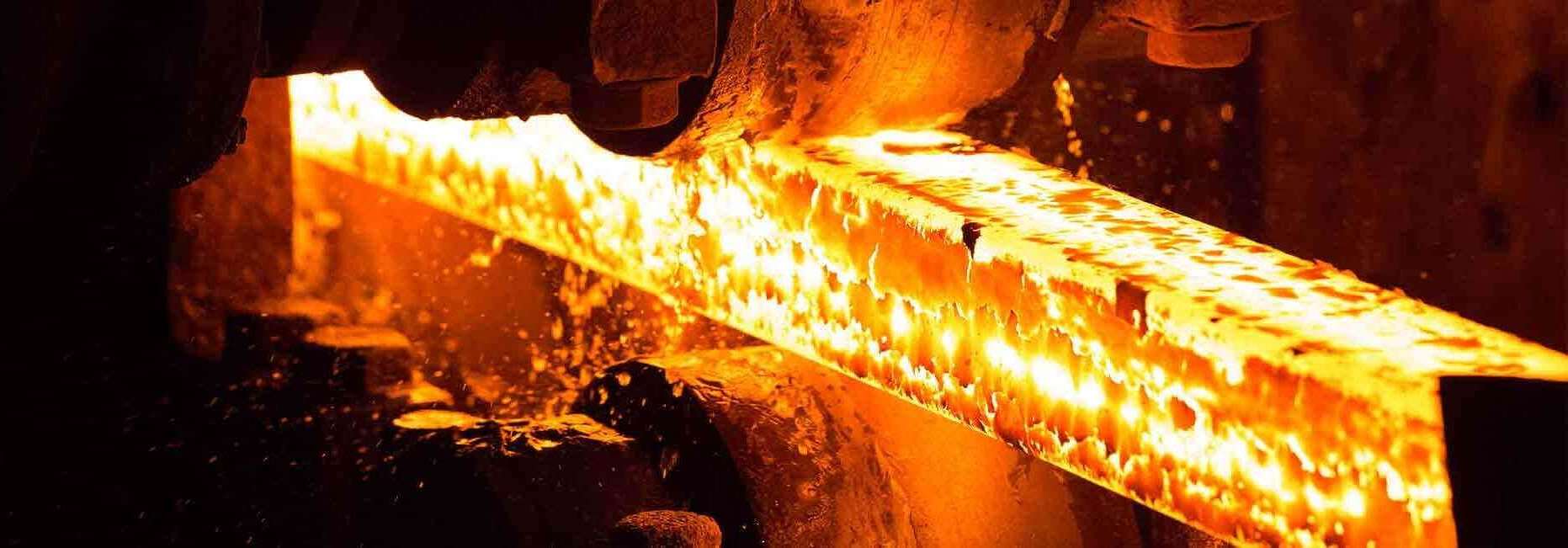
Optimizing Tool Steel Plate Selection for Precision Mould Bases: A Comprehensive Guide
So I've spent the last few years working on injection molds, particularly precision mold bases that demand high quality and durable materials—especially tool steel plates. Selecting the right type is not only an investment but also a science. Today we’ll go through my experiences navigating the world of mold base engineering, from identifying what's crucial about tool selection to avoiding common traps when you're trying to figure out “how to remove base moulding" during maintenance checks or equipment failures. If you're like I was, struggling to understand why some materials work well in specific environments while others crack under minor stresses—this post is tailored exactly for your situation.
Differences Between Various Tool Steels in Terms of Use & Performance (My Take)
I created this quick-reference table after reviewing several datasheets and real application examples where tool plate performance varied greatly based on material properties. Let’s take a look.
| Material | Durability (out of 10) | Corrosion Resistance (Out of 5) | Machinabilty | Cavity Life Approximation (cycles) | Ideal For |
|---|---|---|---|---|---|
| H13 | 9 | 3 | Fair | ~1,000,000+ | Hot forging die blocks/moving parts |
| A2 | 8 | 2 | Easy-to-mill options | ~700,000 | Cold stamping/cam-driven systems |
| P20 + Ni | 7 | 4 | Better than average | ~200k-300k | Budget-oriented plastic part tools (non-abrasive) |
| S7 | 7 | 2 | Challenging cuts but tough as hell under impact loads | n/a | Shock-prone applications like drop-hammers |
Listed: Key Factors Influencing Tool Steel Decision (What Works for Me)
- Hardness requirements vary by pressure exposure: softer alloys deform easily over time under high heat, which kills precision molds
- Evaluation of polish finish expectations (high-grade P20 gives better surfaces pre-finishing)
- Cost vs. lifespan calculations matter big-time; especially when using H13 steels
- Select pre-hardened materials for CNC-edged projects with no post-process heat treatments planned at all
- Maintenance costs increase if corrosion resistance is poor—you’ll need protective coating cycles and frequent cleaning procedures
Cooper Grate Applications – What’s That Got to Do with Molds?
This section isn’t random! When working inside industrial foundry spaces and cooling system designs related to large castings molds run into issues involving excessive heat buildup, engineers began installing something called Cooper grated structures under floor support layers of large-scale molds to help displace heat effectively across production bays.
An Anecdote:
On one project I recall in detail—a huge mold press room kept failing every week despite replacing water jacket insulation constantly—we finally identified that air recirculation zones were heating components far quicker than their cooling systems managed. After inserting Copper grates into structural gaps between slab foundation areas (to conduct excess heat away from critical regions near ejector bushings) things started cooling down much smoother and faster!

Realistic Failure Analysis: Tool Plate Degradation Issues (That Solved My Cracks)
No one likes cracking problems halfway through production runs—but it's always good to ask yourself how you’re handling these three elements:
- Was there uneven grinding or improper polishing causing stress risers?
- If so, does your machine shop team double-check microfractures via magnetic inspection?
- Check whether thermal cycling was handled smoothly in prior steps like tempering after welding repairs.
In short: avoid overheating localized sections during EDM processing—and check the final pass depth of finish cutters. These two factors often cause internal tension that leads directly to premature failure even before reaching rated cavity cycle limits!
Troubleshooting Checklist During Mold Plate Failures
If you see unusual cracks or unexpected wear early in mold life cycles—I highly suggest referring to the following basic inspection guide. These are points I personally developed after inspecting several dozen faulty tool sets and comparing root cause patterns from them.
| Step # | Area Checked | Issue Found / Observed? | Action Needed |
|---|---|---|---|
| 1 | Surface Hardness Consistency Across Plate Faces | Yes - variation exceeds Rockwell C 6% | Retailer needs new supplier; check calibration logs next run. |
| 2 | Thermal Shock Testing Reports | Lack of proper annealing history available. | Contact vendor—get data or replace source. |
| 3 | Post-Quench Stress Patterns Detected Visually/Through Equipment Readings | Found significant stress zones along core mounting holes. | Mention to engineer for revised relief groove dimensions next build version. |
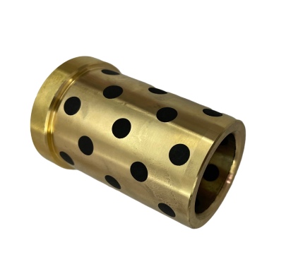
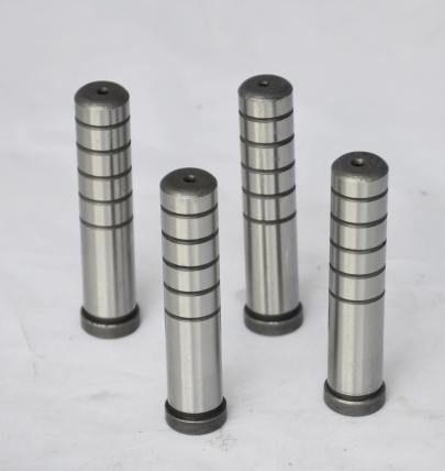
| 4 | Mechanical Alignment of Ejector Housing Area Post Installation | Sliding friction damage noted near ejection zone supports. | Create tighter clearance fits with polished bushing guides here going forward |
“How to Remove Base Moulding"—My Personal Technique (Saves Tools!)
A lot of folks just hammer off worn moldings carelessly—damaging underlying plates badly and requiring costly surface reworking after each change. That used to be my mistake until an older engineer gave me this tip:
If the "how to remove base mould" search keeps returning wrong methods—it’s best practice to gently pry upwards first using aluminum jacking spindles placed under key junction points.
The moment I learned this, I started doing light tap tests first—checking whether any fasteners remained connected beneath panels before forcing removals headfirst! It helps preserve original machining edges far longer than expected and lowers total mold replacement rate significantly.
A little-known trick: Apply a tiny shot blast pattern or sand-belt edge wear lines along panel interfaces that need future disassembly. These markers act as release indicators showing if separation occurs slowly rather than abruptly—which again extends useful service lifespans dramatically.
Summary of Key Material Criteria I Look For in Tool Steel Sheets Today
I keep these top four criteria in mind now every single purchase review process because I’ve suffered from poor decisions otherwise earlier in my work phase.
- Vickers rating must align strictly according to cavity load predictions
- No unpolished pits—especially near runner channels where erosion starts fastest
- Avoid suppliers without detailed hardness gradient reports; always insist upon sample testing unless certified sources used directly.
- Ask about secondary grain structure characteristics—they heavily influence long-cycle performance outcomes more than commonly advertised!
Conclusion – My Last Thoughts From Years Managing Real World Injection Molding
If there’s anything that changed after working extensively with various grades, types, coatings and manufacturing histories around MOLD BASE TOOL STEEL SELECTIONS, it would definitely include taking full control of decision making around both raw plate sourcing AND post-install maintenance schedules for our tool teams. Yes I still occasionally encounter problems with certain casting geometries pushing plate durability beyond specs—but nowadays they’re easy enough to anticipate if you’ve already considered these parameters in your checklist way upfront. To those who may feel unsure choosing a particular mold base material specification for tool sheets: don’t rush the decision. Your choice will dictate the overall performance—not just the first trial rounds, but the next hundred thousand production hours ahead of time. Trust in your numbers, test thoroughly if you can—and remember to check what the guys actually assembling those cores and cavities recommend themselves. Because at the end of the day… the mold never lies!